Electrophysiology catheter

Active Publication Date: 2011-11-10
KONINKLIJKE PHILIPS ELECTRONICS NV
View PDF26 Cites 7 Cited by
  • Summary
  • Abstract
  • Description
  • Claims
  • Application Information

AI Technical Summary

Benefits of technology

[0016]The invention is particularly, but not exclusively, advantageous for obtaining information for an operator of which side of the EP catheter that touches the wall, which again enables the operator to steer the advancing catheter more precisely. This makes faster and safer advancement of EP catheters possible.
[0040]The invention is particularly, but not exclusively, advantageous for obtaining a reference signal which allows artefacts induced by the gradient field of an MRI apparatus to be efficiently and easily removed. This makes it simpler to filter EP signals and thereby decreases cost and complexity of MR-EP catheter systems.

Problems solved by technology

Typical electrophysiology (EP) catheters have limited steering possibilities, and can usually only be bent in one direction transverse to the extent of the distal end of the catheter.
Steering catheters in patients is sometimes performed under guidance of a medical imaging modality, e.g. magnetic resonance imaging (MRI), but even this does not allow the operator to directly determine the catheter roll angle in relation to patient anatomy.
It is thereby a disadvantage that roll angle information is not directly available to the operator of EP catheters.
Another problem when EP catheters are used in MRI environments is the presence of artefacts on the measured EP signal caused by the MR system.
Filtering these signals to reduce artefacts based on the gradient signal from the MRI apparatus is troublesome, as extracting and scaling an electrical signal proportional to the induced artefact is not simple.
Furthermore, the relation of the gradient waveform to the actual artefact is often ambiguous.
It is thereby a disadvantage that gradient induced artefacts on signal measured by EP catheters in MRI environments cannot be efficiently filtered.

Method used


Image

  • Electrophysiology catheter
  • Electrophysiology catheter
  • Electrophysiology catheter

Examples


Embodiment Construction

[0057]The basic hardware for use in various embodiments of the invention will be described in the following in relation to FIGS. 1 through 3.

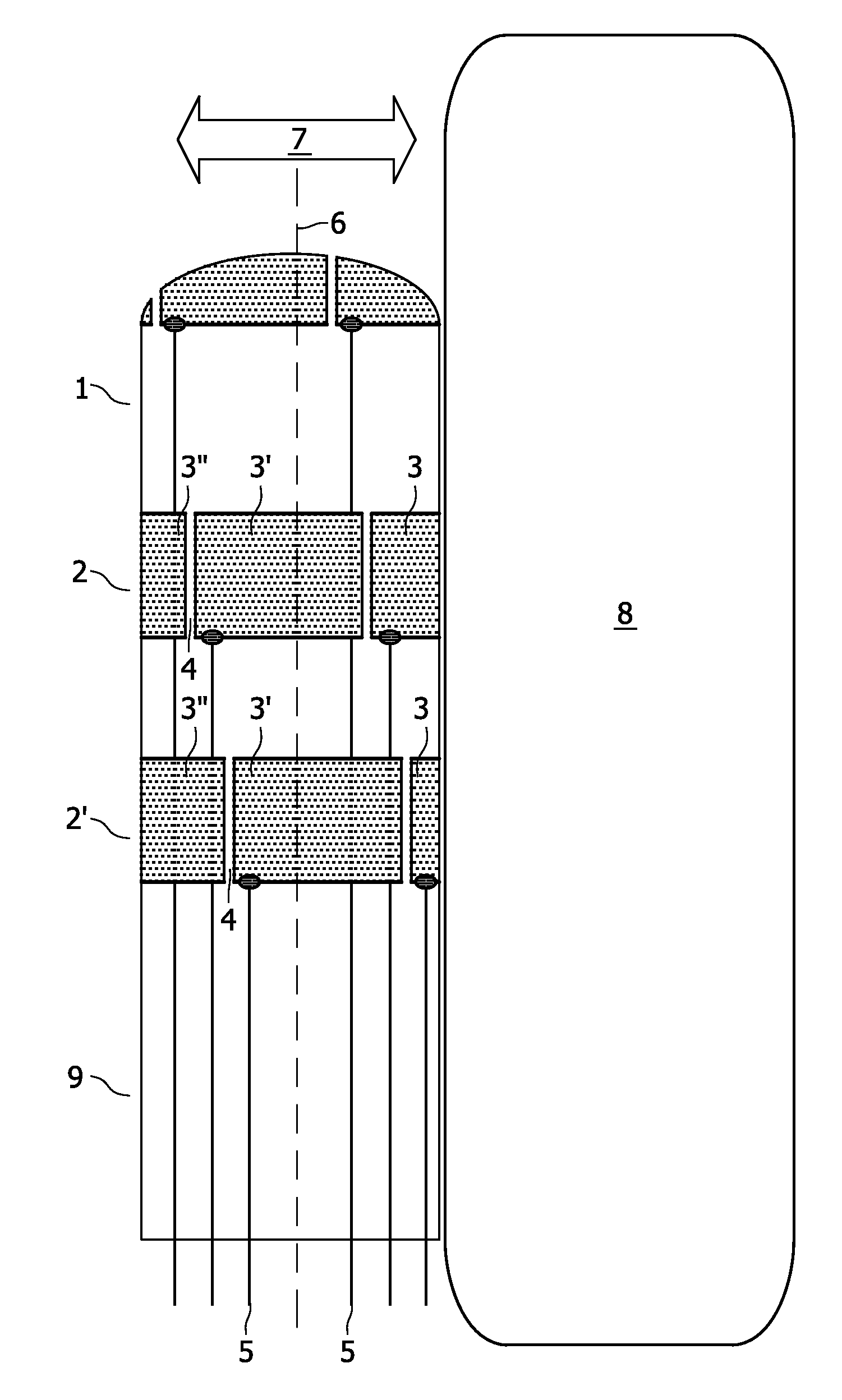
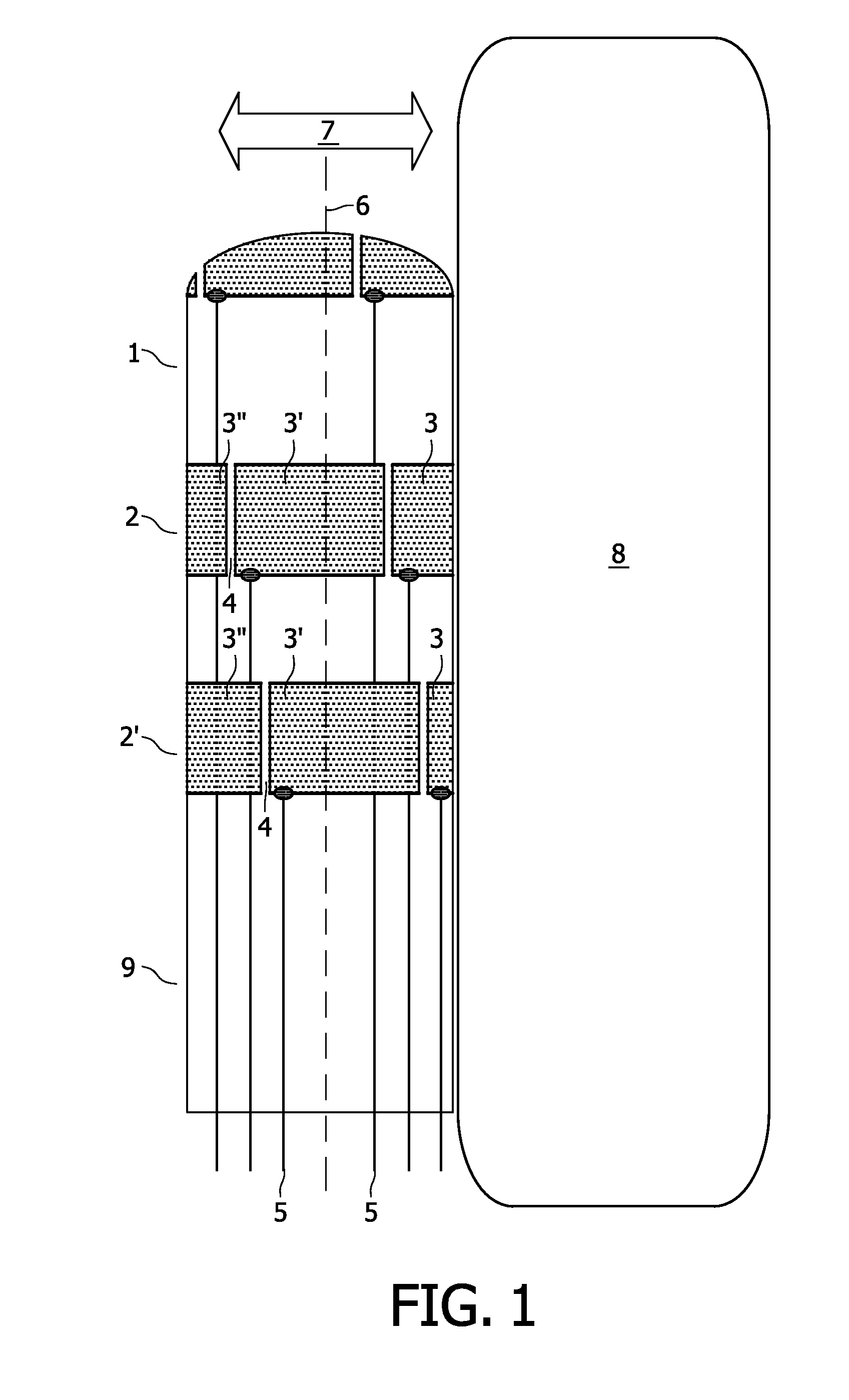
[0058]FIG. 1 shows a distal end portion 1 of an EP catheter 9 according to various embodiments of the invention. A centre axis for the distal end portion is illustrated by punctured line 6. Distal end portions of catheters are normally bendable to facilitate steering of the catheter during advancement in a patient. Arrow 7 illustrates a bending direction of the distal end portion 1 being transverse to the centre axis 6.

[0059]Electrode segments 3 (3′, 3″) are arranged in bands 2 around the end portion to detect and thereby map electrophysiological signals in patient anatomy. It is customary to have many bands, such as around 20 bands, around such EP catheter. The electrode segments are separated by slits 4 to electrically isolate them from each other.

[0060]It is preferred that such slits 4 are narrow to avoid dead regions with no electrode cover...


PUM


Abstract

The invention relates to electrophysiology catheter systems and their use, such as in an MRI environment, and in particular to analysis of electric signals from such. An electrophysiology (EP) catheter with a plurality of electrically isolated electrode segments arranged in longitudinally spaced bands around the catheter is used to detect electric signals. A workstation receives the electrical signals which are then processed by a processing unit. Electric signals from electrode segments can be used to determine roll angle information of the catheter in relation to patient anatomy by determining signals from electrode segments in contact with tissue. Also, electric signals can be used to extract a reference signal that can be used to correct for gradient induced artefacts.

Description

FIELD OF THE INVENTION[0001]The present invention relates to electrophysiology catheters, in particular to analysis of electric signals from such.BACKGROUND OF THE INVENTION[0002]Typical electrophysiology (EP) catheters have limited steering possibilities, and can usually only be bent in one direction transverse to the extent of the distal end of the catheter. Using this bending in combination with twisting or rolling the catheter to adjust a roll angle and thereby the direction of the bending, are the manoeuvres the operator uses to steer the catheter through the patient anatomy. It is therefore of importance for the operator to control the roll angle in relation to the patient anatomy, as this is needed to be able to bend the catheter tip in the right direction.[0003]Steering catheters in patients is sometimes performed under guidance of a medical imaging modality, e.g. magnetic resonance imaging (MRI), but even this does not allow the operator to directly determine the catheter r...

Claims


Application Information

Patent Timeline
IPC IPC(8): A61B5/053A61B5/04
CPCA61B5/0422A61B5/287
Inventor LIPS, OLIVERDAVID, BERNDKRUEGER, SASCHAWEISS, STEFFEN
Owner KONINKLIJKE PHILIPS ELECTRONICS NV
Why Eureka
Try Eureka