Method for carburizing workpieces and its application

a technology for carburizing workpieces and workpieces, applied in the direction of mechanical equipment, solid-state diffusion coatings, machines/engines, etc., can solve the problem of workpiece manufacturing, and achieve the effect of great surface hardness and great surface hardness

Inactive Publication Date: 2011-11-17
ROBERT BOSCH GMBH
View PDF3 Cites 21 Cited by
  • Summary
  • Abstract
  • Description
  • Claims
  • Application Information

AI Technical Summary

Benefits of technology

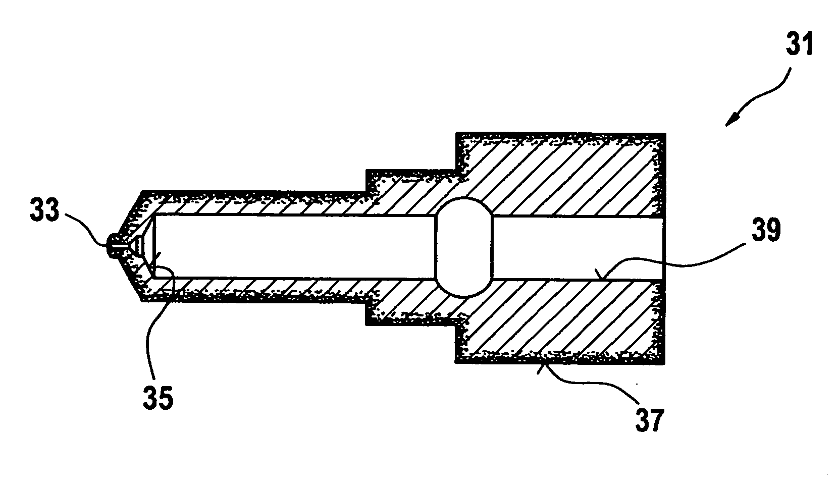
[0032]By contrast, it is necessary, however, to provide a great surface hardness in the area of the guideway of the valve member. The wear on the nozzle body, caused by the movement of the valve member, is able to be reduced because of the great surface hardness. In addition, a great rigidity in the area of the guideway of the valve member is required. This is also achieved by great surface hardness.
[0033]Because of the application of the method according to the present

Problems solved by technology

A disadvantage of this method is that the workpiece has to be manufactured oversized, so that

Method used


Image

  • Method for carburizing workpieces and its application
  • Method for carburizing workpieces and its application

Examples


Embodiment Construction

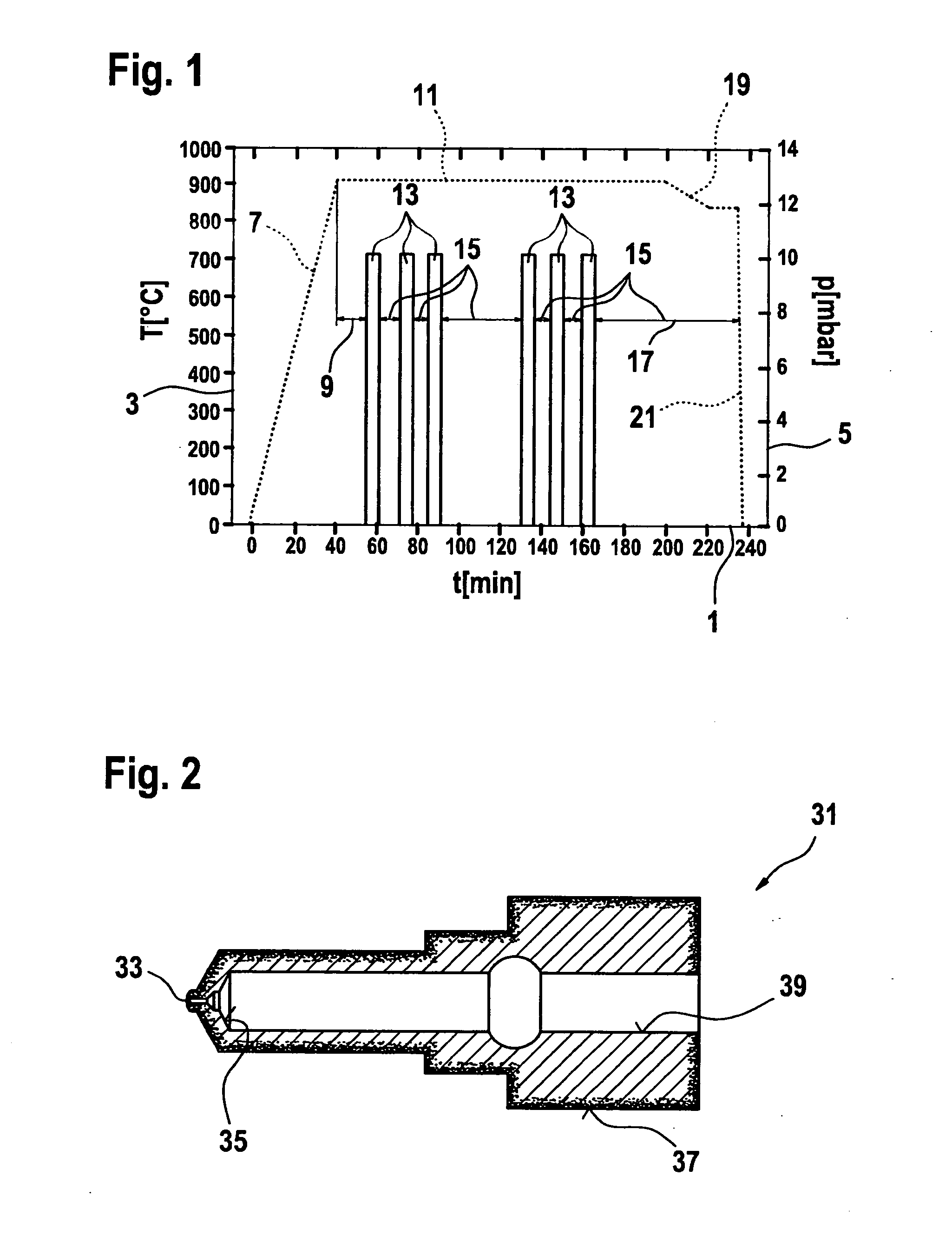
[0037]FIG. 1 shows the pressure and temperature curves as a function of time for the method according to the present invention.

[0038]The method for carburizing workpieces made of steel is generally performed at low pressure operation. During the carburizing of the workpiece, the pressure is generally within the range of 1 to 30 mbar, in this context. The pressure may be in the range from 4 to 10 mbar.

[0039]In the diagram shown in FIG. 1, time t is plotted on abscissa 1, temperature T is plotted on ordinate 3 and pressure p is plotted on second ordinate 5.

[0040]In the method according to the present invention, the workpiece is heated to carburizing temperature in a first step 7. The carburizing temperature is generally in the range of 880 to 1050° C., which may be in the range of 900 to 1000° C. The temperature at which the workpiece is exposed to a carburizing atmosphere is designated as the carburizing temperature, in this context.

[0041]After being heated to casehardening temperatu...


PUM

PropertyMeasurementUnit
Temperatureaaaaaaaaaa
Timeaaaaaaaaaa
Timeaaaaaaaaaa

Abstract

A method for carburizing workpieces made of steel, particularly workpieces having outer and inner surfaces, the workpiece being held at a temperature in the range of 850 to 1050° C. in an atmosphere containing a gaseous hydrocarbon. At least two different gaseous hydrocarbons are used and/or the workpiece is alternatingly held in the atmosphere containing the gaseous hydrocarbon during a carburizing pulse and in an atmosphere free of hydrocarbon during a diffusion phase. Also described is a use of the method.

Description

FIELD OF THE INVENTION[0001]The present invention relates to a method for carburizing workpieces made of steel, particularly workpieces having outer and inner surfaces. The present invention also relates to an application of the method.BACKGROUND INFORMATION[0002]Methods for carburizing workpieces made of steel are used to harden the surface of the workpieces. In order to do this, in workpieces made of steel the surface layer of a low carbon steel is enriched before hardening of the workpiece takes place.[0003]The carburizing takes place, for example, as low pressure carburizing. To this end, the workpieces are inserted into a vacuum furnace having a process chamber, to perform the carburizing. The process chamber has a process gas, that gives off carbon, flowing through it, in order to enrich the surface region of the workpieces with carbon.[0004]In low pressure carburizing having thermal decomposition of the process gas, generally of hydrocarbons, in the process chamber, the proce...

Claims


Application Information

Patent Timeline
IPC IPC(8): C23C8/22C21D1/06C21D1/76
CPCC23C8/20F02M2200/9038F02M61/166C23C8/22
Inventor FOERSTER, LOTHARSCHWARZER, JOCHENWALDENMAIER, THOMAS
Owner ROBERT BOSCH GMBH
Why Eureka
Try Eureka