
Sample and hold circuit and a/d converter apparatus

Active Publication Date: 2011-11-17
TOYOTA JIDOSHA KK
View PDF9 Cites 30 Cited by
  • Summary
  • Abstract
  • Description
  • Claims
  • Application Information

AI Technical Summary

Problems solved by technology

Thus, if the above offset cancelling method is used in the conventional sample and hold circuit mentioned above, an error due to the mismatch of the parasitic capacitances between the two capacitors would remain without being cancelled as an input offset of the operational amplifier.
As a result, an accurate sample-and-hold output may not be obtained.

Method used


Image

  • Sample and hold circuit and a/d converter apparatus
  • Sample and hold circuit and a/d converter apparatus
  • Sample and hold circuit and a/d converter apparatus

Examples


embodiment 1

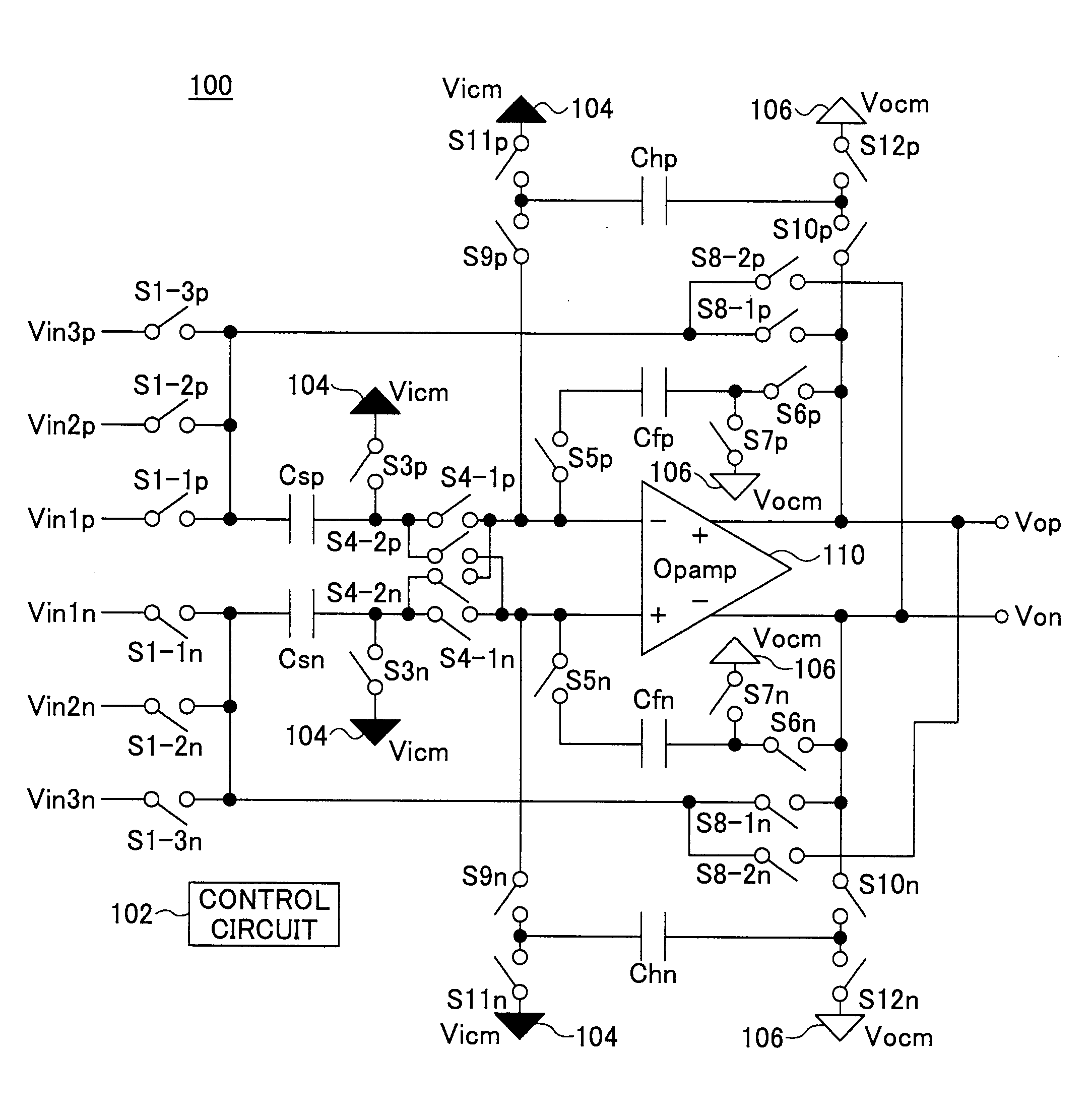
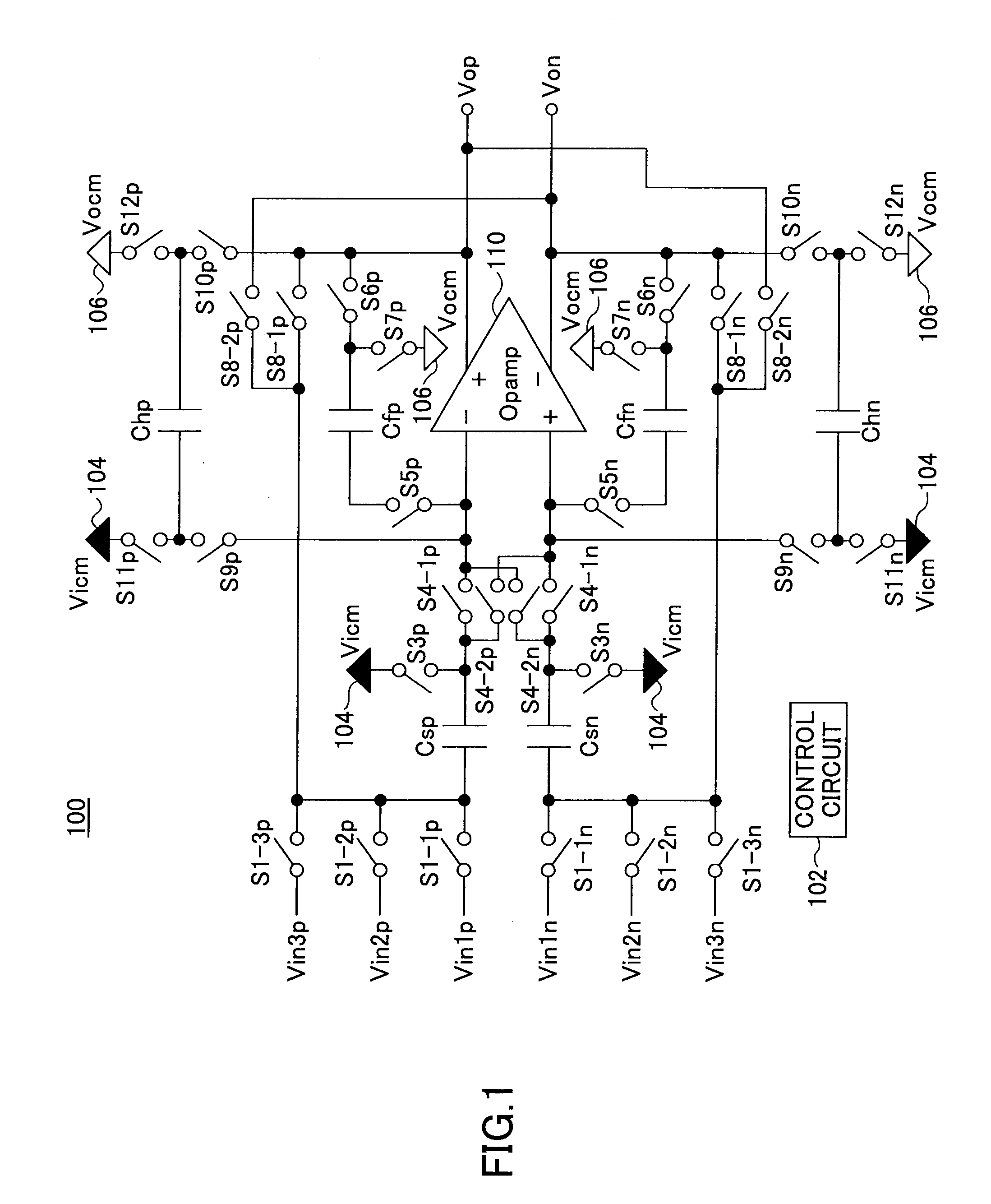
[0030]Referring now to the drawings, wherein like reference numerals designate identical or corresponding parts throughout the several views, FIG. 1 illustrates a sample and hold circuit 100 according to an embodiment of the present invention. The sample and hold circuit 100 is of a differential input type configured to sample and hold a potential difference between two analog input voltages, and then produces a hold output. The sample and hold circuit 100 may be used in an analog-to-digital converter (ADC) apparatus (such as a cyclic ADC or a pipe-lined ADC) for converting an input analog voltage into a digital value.

[0031]As illustrated in FIG. 1, the sample and hold circuit 100 includes a pair of capacitors Csp and Csn capable of sampling two analog input voltages. The capacitors Csp and Csn are hereafter referred to as sampling capacitors Csp and Csn having capacitances of Csp and Csn, respectively. An input terminal of the sampling capacitor Csp may be supplied with an analog p...

embodiment 2

[0074]FIG. 12 illustrates a sample and hold circuit 200 according to another embodiment of the present invention. The sample and hold circuit 200 is of the differential input type configured to sample and hold a potential difference between two input analog voltages. The sample and hold circuit 200 may be applied in an A / D converter apparatus (such as a cyclic ADC or a pipelined ADC) configured to convert an input analog voltage into a digital value. The sample and hold circuit 200 is capable of producing a highly accurate sample-and-hold output and performing a highly accurate A / D conversion even when the level of a differential input voltage Vin′ (=Vinp−Vinn) varies over a wide range exceeding a power supply voltage (VDD−VSS).

[0075]Referring to FIG. 12, in the sample and hold circuit 200, an analog potential Vinp is inputted to the input terminal of the sampling capacitor Csp via a switch S1p. An analog potential Vinn is inputted to the input terminal of the sampling capacitor Csn...


PUM


Abstract

A sample and hold circuit includes an operational amplifier; a sampling capacitor configured to sample input voltages at a plurality of different timings; an adding / subtracting unit configured to perform an adding or subtracting operation of the input voltages sampled by the sampling capacitor; and an offset voltage removing unit configured to remove an input offset voltage component of the operational amplifier from a voltage obtained by the adding or subtracting operation. The operational amplifier is configured to produce an output by holding the voltage from which the input offset voltage component of the operational amplifier has been removed by the offset voltage removing unit.

Description

BACKGROUND OF THE INVENTION[0001]1. Field of the Invention[0002]The present invention generally relates to sample and hold circuits and A / D converter apparatuses. Particularly, the invention relates to a sample and hold circuit suitable for use in a process of converting an input analog voltage into a digital value, and an A / D circuit including the sample and hold circuit.[0003]2. Description of the Related Art[0004]A sample and hold circuit is known in which an operational amplifier is used for performing a sampling and holding operation. In this type of a sample and hold circuit, the operational amplifier often employs a MOS transistor input configuration having a high input impedance. The operational amplifier of the MOS transistor input configuration, however, tends to have a large offset voltage compared to an operational amplifier having a bipolar input configuration because the element threshold voltage of the MOS transistor tends to have large variations. A method of cancell...

Claims


Application Information

Patent Timeline
IPC IPC(8): G11C27/02
CPCG11C27/026
Inventor WATANABE, HIKARU
Owner TOYOTA JIDOSHA KK
Learn More