
Differential transmission circuit and electronic device provided with the same

Active Publication Date: 2011-11-17
PANASONIC CORP
View PDF17 Cites 24 Cited by
  • Summary
  • Abstract
  • Description
  • Claims
  • Application Information

AI Technical Summary

Benefits of technology

According to the differential transmission circuit and the electronic device including the differential transmission circuit, a part of a current of an electrostatic pulse applied to the first and second transmission lines is routed to the ground by the first and second ESD protection elements. In addition, a current of an electrostatic pulse, which is not completely dropped by the first and second ESD protection elements, is bypassed to the ground by the first and second ESD protection diodes provided at a subsequent stage, and it is possible to suppress a current from flowing into a load (for example, LSI) connected to the first and second resistors by the first and second resistors provided at a further subsequent stage.
Due to the above-described operation, it is possible to provide a differential transmission circuit capable of securing a high resistance to electrostatic breakdown while suppressing deterioration of a transmission signal in a high-speed transmission circuit to the minimum, and an electronic device including the differential transmission circuit.

Problems solved by technology

However, in terms of the configuration of these protection diodes, each of them maintains a capacitance component, such that the capacitance value becomes large when the protection diodes are connected in a multi-stage manner, and therefore this configuration has an adverse effect on a signal of a high-frequency band.
Therefore, in the LSI used in a high-speed transmission line or the like, the protection elements that can be embedded are restricted, and accordingly, the resistance to the electrostatic breakdown is deteriorated.

Method used


Image

  • Differential transmission circuit and electronic device provided with the same
  • Differential transmission circuit and electronic device provided with the same
  • Differential transmission circuit and electronic device provided with the same

Examples


Embodiment Construction

Hereinafter, a differential transmission circuit according to an embodiment of the invention will be described using FIGS. 1 to 9.

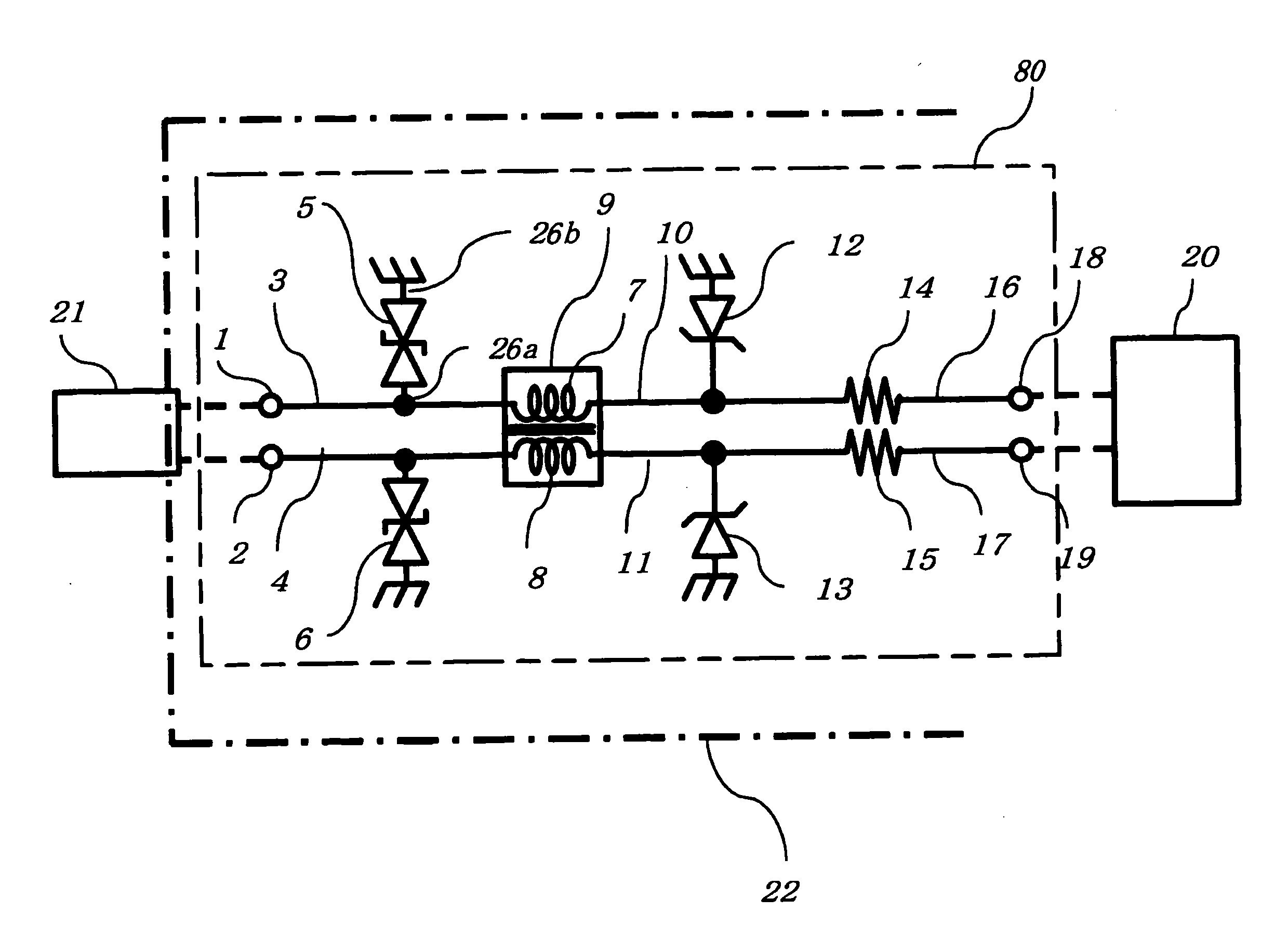
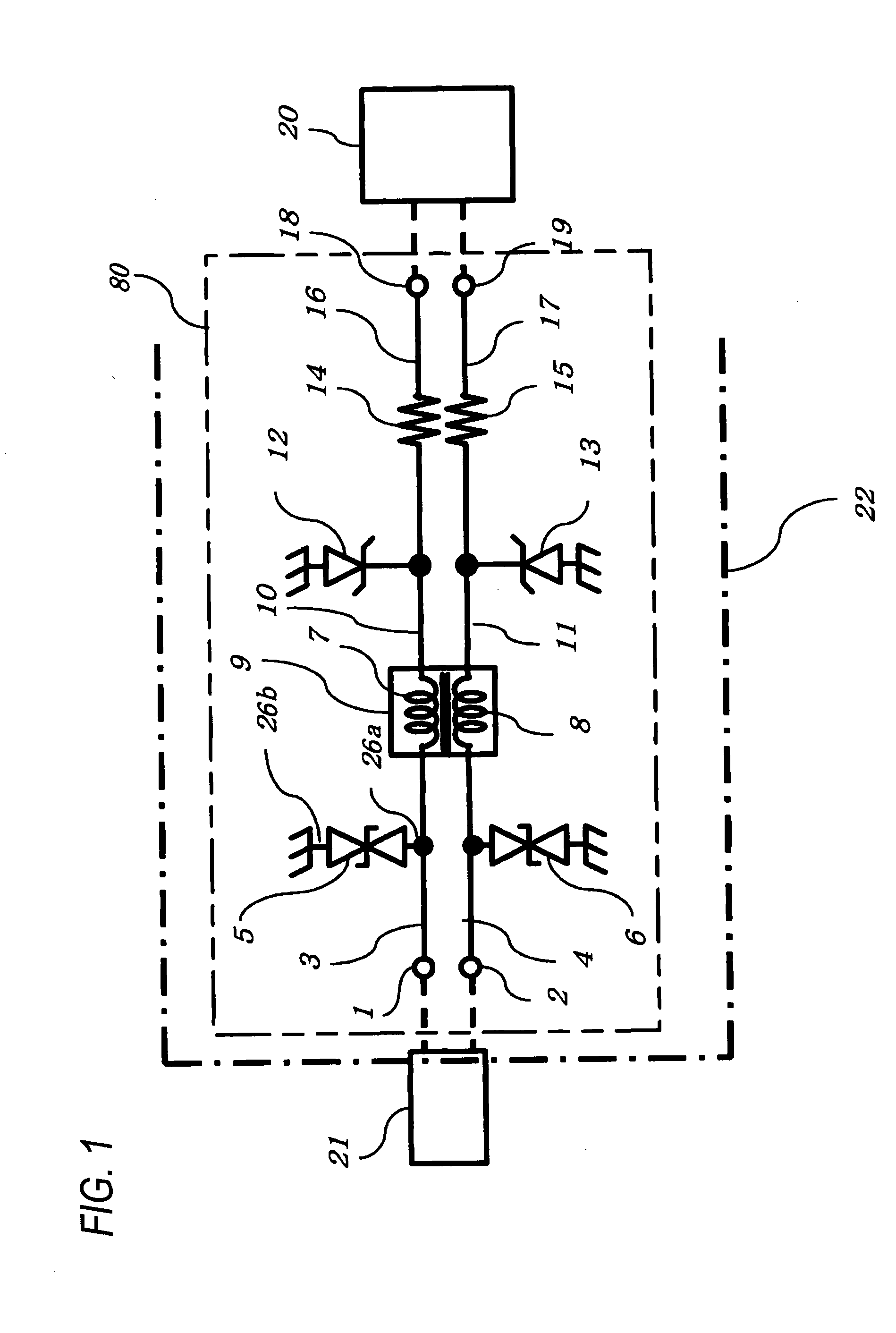
FIG. 1 shows a schematic diagram illustrating a configuration of a differential transmission circuit 80 according to an embodiment of the invention.

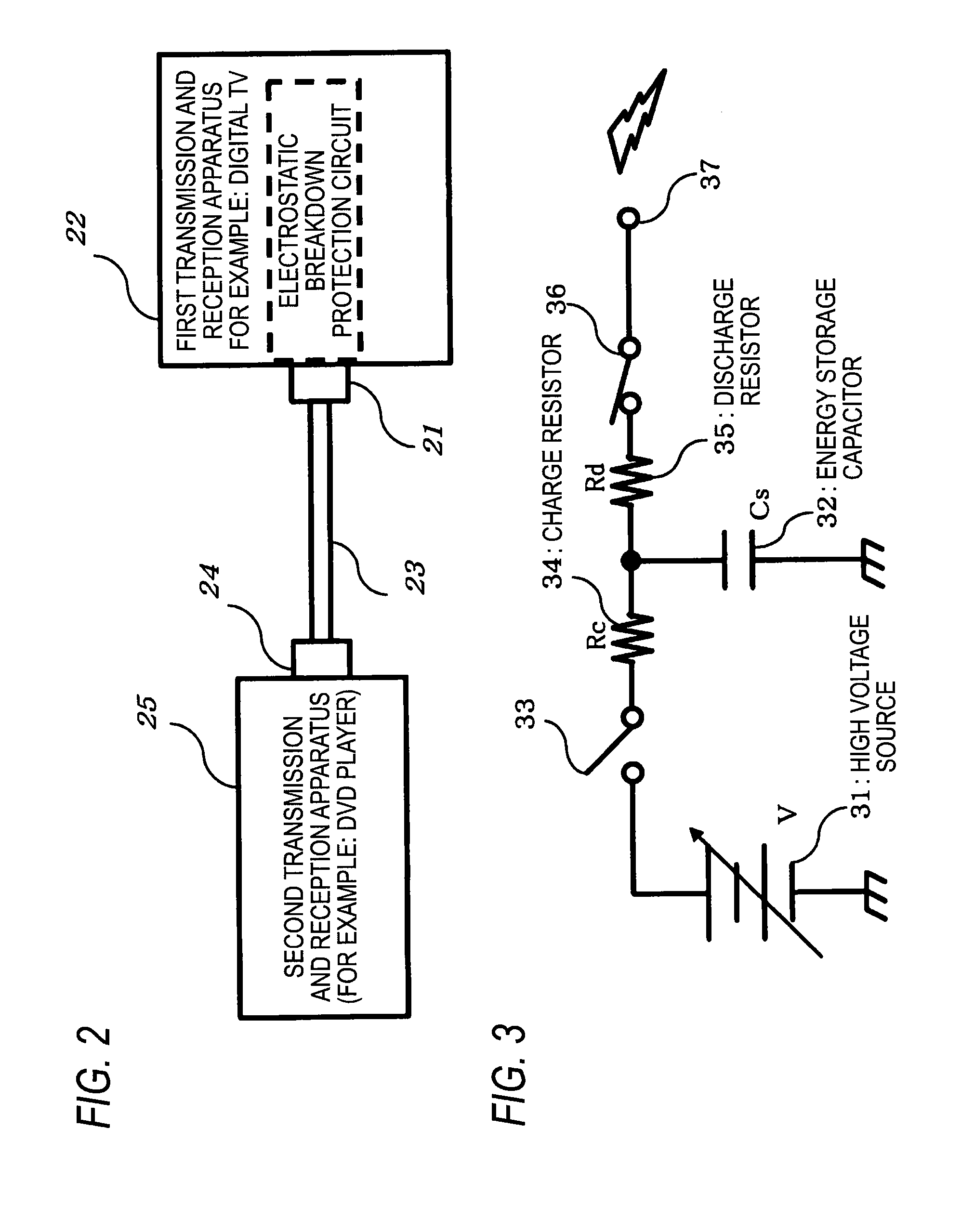
As shown in FIG. 1, the differential transmission circuit 80 is accommodated in a first transmission and reception apparatus 22 such as a digital TV, and includes a first transmission line 3 connected to a first input and output terminal 1, a second transmission line 4 connected to a second input and output terminal 2, a first ESD protection element 5 connected between the first transmission line 3 and a ground, and a second ESD protection element 6 connected between the second transmission line 4 and a ground. Electrostatic capacitance values of the first and second ESD protection elements 5 and 6 are selected to be substantially 0.3 pF or less.

The differential transmission circuit 80 further includes a commo...


PUM


Abstract

There is disclosed a differential transmission circuit capable of realizing a high resistance to electrostatic breakdown without deteriorating a transmission signal. The differential transmission circuit includes ESD protection elements 5 and 6 connected between transmission lines 3 and 4 and a ground, respectively, a common mode filter 9 in which an inductor element 7 serially connected between the transmission lines 3 and a transmission line 10, and an inductor element 8 serially connected between the transmission line 4 and a transmission line 11 are magnetically coupled to each other, ESD protection diodes 12 and 13 of which cathodes are connected to the transmission lines 10 and 11, respectively, and anodes thereof are connected to grounds, respectively, and resistors 14 and 15 of which one side terminals are connected to the transmission lines 10 and 11, respectively, and the other side terminals thereof are connected to transmission lines 16 and 17, respectively. Resistance values of the resistors 14 and 15 are set to 10 to 15 ohms, respectively, electrostatic capacitance values of the ESD protection elements 5 and 6 are less than 0.3 pF, respectively, and a clip voltage of each of the ESD protection diodes 12 and 13 is set to a value less than 10 V.

Description

This application is a U.S. National Phase Application of PCT International Application PCT / JP2010 / 000514.TECHNICAL FIELD The present invention relates to a differential transmission circuit that is used for protecting an electronic apparatus including a high-speed signal transmission circuit such as an HDMI (High-Definition Multimedia Interface) from static electricity, and an electronic device including the differential circuit.BACKGROUND ART In recent years, along with higher performance and higher functionality in regard to digital apparatuses, increases in data transmission speeds and increases in bandwidth have been progressing quickly. To cope with this, standards for a high-speed data transmission beginning with an HDMI have been spreading quickly.In addition, as represented by a portable apparatus, a mobile phone, an in-vehicle apparatus, or the like, the locations at which these apparatuses are used have increased regardless of being indoors or outdoors, and therefore high...

Claims


Application Information

Patent Timeline
IPC IPC(8): H02H9/04
CPCH03H7/427H03H7/0107
Inventor IWASA, MASAHARUYAMADA, TOMOHIRO
Owner PANASONIC CORP
Features
  • Generate Ideas
  • Intellectual Property
  • Life Sciences
  • Materials
  • Tech Scout
  • Unparalleled Data Quality
  • Higher Quality Content
  • 60% Fewer Hallucinations
Learn More