Methods and systems for extending the range for fiber optic distributed temperature (DTS) systems

Inactive Publication Date: 2011-11-17
SENSORTRAN
View PDF11 Cites 18 Cited by
  • Summary
  • Abstract
  • Description
  • Claims
  • Application Information

AI Technical Summary

Benefits of technology

[0011]The scheme includes a method for extending the distance range of a fiber optic distributed temperature system comprising the steps of: transmitting, in a first time period, a first optical signal at a first energy level through an optical fiber; collecting backscatter signals as a result of the first transmission; transmitting, in at least one additional time period, an

Problems solved by technology

The resulting distributed measurement is equivalent to deploying a plurality of conventional point sensors, which would require more equipment and increase operational costs.
Each conventional electrical point sensor would require multiple electrical leads and this would add to a large and expensive cable bundle as the number of point sensors increase.
One problem with current systems and techniques is the ability to measure these parameter profiles over an extended distance, where the optical signal tends to degrade due to the attenuation along the fiber.
For these reasons, increasing the light energy by increasing the laser power is not a viable

Method used


Image

  • Methods and systems for extending the range for fiber optic distributed temperature (DTS) systems
  • Methods and systems for extending the range for fiber optic distributed temperature (DTS) systems
  • Methods and systems for extending the range for fiber optic distributed temperature (DTS) systems

Examples


Embodiment Construction

[0023]In the following detailed description, reference is made to the accompanying drawings that illustrate embodiments of the present invention. These embodiments are described in sufficient detail to enable a person of ordinary skill in the art to practice the invention without undue experimentation. It should be understood, however, that the embodiments and examples described herein are given by way of illustration only, and not by way of limitation. Various substitutions, modifications, additions, and rearrangements may be made without departing from the spirit of the present invention. Therefore, the description that follows is not to be taken in a limited sense, and the scope of the present invention is defined only by the appended claims.

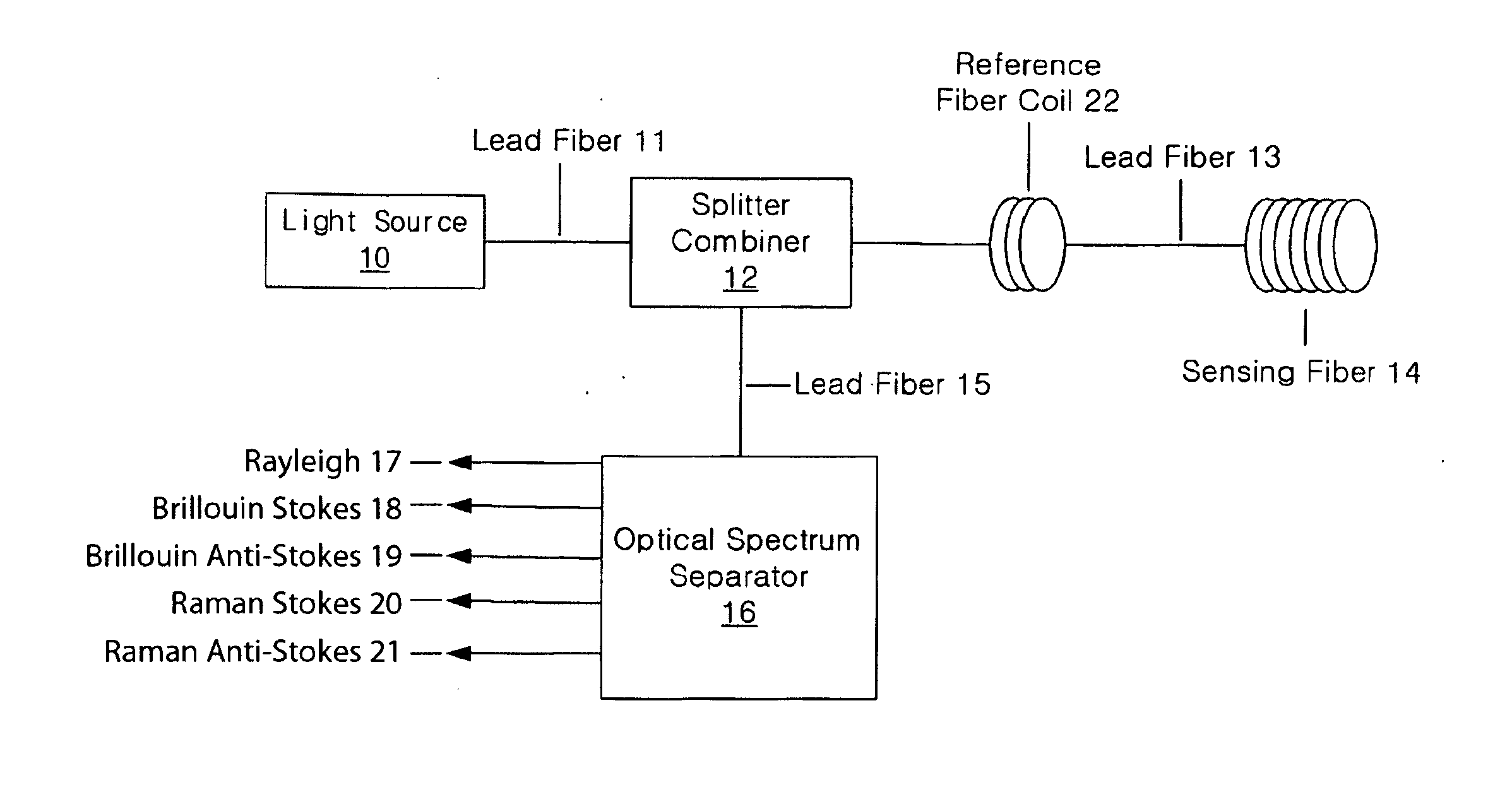
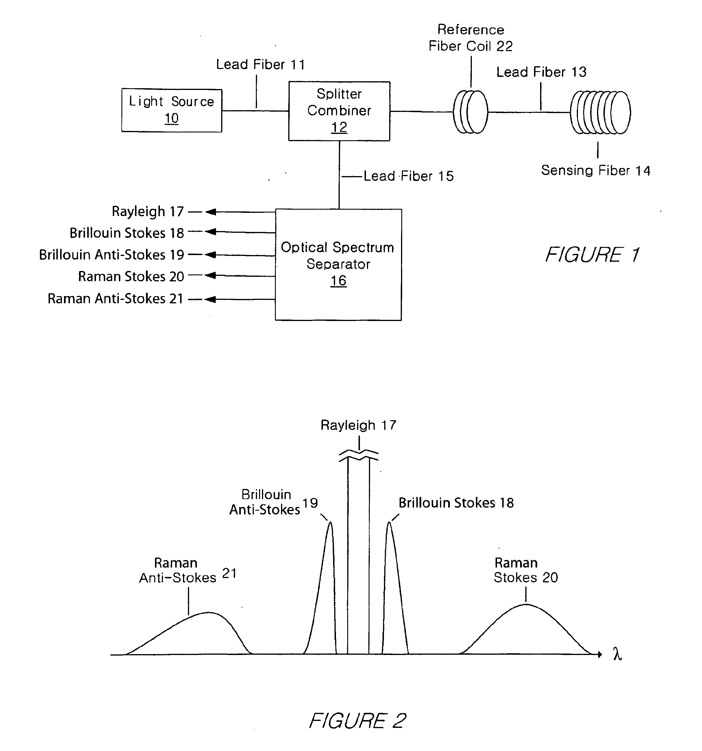
[0024]FIG. 1 illustrates a conventional DTS system, including a light source 10, a lead fiber 11, a light splitter and combiner 12, lead fiber 13 and 15, a sensing fiber 14, optical spectrum separator 16, Rayleigh component 17, Brillouin Stok...


PUM


Abstract

Systems and methods for extending the range of a fiber optic DTS system are provided. In one respect, a method may provide steps for transmitting, in a first time period, an optical signal at a first energy level through an optical fiber, collecting backscatter signals as a result of the first transmission, adjusting the first energy level to a second energy level, transmitting, in an additional time period, the adjusted optical signal through the optical fiber, collecting backscatter signals as a result of the adjusted transmissions, and using a portion of the collected backscatter as a result of the first transmission and a portion of the collected backscatter as a result of the additional transmissions, determining one or more parameter profiles, such as a temperature profile.

Description

CROSS REFERENCE TO RELATED APPLICATIONS[0001]This application claims the benefit of U.S. provisional Ser. No. 61 / 022,225 filed Jan. 18, 2008.BACKGROUND[0002]This disclosure relates generally to distributed temperature sensing (DTS) systems and, more particularly, to methods and systems for extending the range of fiber optic DTS systems.[0003]For several years, fiber optic sensors, and in particular, DTS systems, have provided higher bandwidth, inherently safe operation (no generation of electric sparks), and immunity from EMI (Electromagnetic Interference) for parameter measurements.[0004]For example, the temperature profile parameter and other parameter profiles along the fiber can be monitored. The resulting distributed measurement is equivalent to deploying a plurality of conventional point sensors, which would require more equipment and increase operational costs. Each conventional electrical point sensor would require multiple electrical leads and this would add to a large and ...

Claims


Application Information

Patent Timeline
IPC IPC(8): G01N21/47G01K3/00G01K11/32
CPCG01K11/32
Inventor CHUNG, LEEKENT, KALARAJGAONKAR, MAHESHSANDERS, MICHAEL
Owner SENSORTRAN
Why Eureka
Try Eureka