Carpet unit comprising optical sensor

a technology of optical sensors and carpets, applied in the field of carpet units, can solve the problems of inability to use and inability to achieve optical fibers that stick through carpets, etc., to achieve the effect of reducing light absorption, facilitating light outcoupling, and improving light distribution

Inactive Publication Date: 2011-11-24
KONINKLIJKE PHILIPS ELECTRONICS NV +1
View PDF0 Cites 11 Cited by
  • Summary
  • Abstract
  • Description
  • Claims
  • Application Information

AI Technical Summary

Benefits of technology

[0095]In a preferred embodiment, the primary backing layer comprises tufts comprising light reflective material. For example, the primary backing is a nonwoven material through which light brown yarns are tufted, the tufted primary backing having a light transmittance of for example 1-2% without pre-coat layer applied. The use of (reflective) tufts may further enable light outcoupling from the carpet and / or improve light distribution and / or reduce light absorption. The reflectivity may for instance be in the range of 10-40%.
[0096]The choice of the materials of the respective layers of the multi layer may further be of relevance for the transmission of the light source light through the carpet tile. In an example, the primary backing layer comprises a material selected from the group consisting of polypropylene (PP), nylon, and jute, especially PP. Further, preferably the pre-coat layer comprises a material selected from the group consisting of a light transmissive latex, a light-transmissive acrylic and light transmissive polyolefin dispersion based material (such as Hypod™ from DOW). In order to make the pre-coat or adhesive light transmissive it should preferably be substantially free from light scattering or light absorbing particles. If this is not possible (for example due to fire retarding properties of these particles), the amount of filler should preferably be reduced as much as possible. Alternatively, the filler should preferably be replaced with another filler that does not scatter light or scatters light less than state of the art fillers as CaCO3. This may be achieved for example by choosing a filler that has a similar optical index of refraction compared to the adhesive material. For example, we have found that Al(OH)3 has a relatively low scattering in combination with latex. We have also found that the use of fillers with a high degree of purity (for example ≧99%) improves the light transmittance (for example, the CaCO3 fillers typically used in carpeting are known to be brownish in color, due to impurities in the CaCO3).
[0097]The vast majority of carpet tiles that are currently produced are using bitumen or an opaque poly(vinyl chloride) layer as tile backing. These tile backings have no light transmittance and thus another material should be used. Therefore, in a further embodiment, the tile backing comprises a material selected from the group consisting of transmissive poly(vinyl chloride) (PVC) or poly(vinyl butyral) (PVB), silicone rubber, or poly(methyl methacrylate) (PMMA), but alternatively a backing based on polypropylene (PP) or polyethylene (PE) may also be used. All these materials can be used as secondary backing having some flexibility and some light transmittance. Thus, any of these light transmissive materials PVC, PVB, silicone rubber, PMMA, etc, may be applied.
[0098]The tile backing also comprises an adhesive, coated to the pre-coat layer. This adhesive layer may optionally comprise the above mentioned scrim. Preferably, the adhesive layer used for the tile backing comprises a material selected from the group consisting of transmissive PVC (poly vinyl chloride), PVB (poly vinyl butyral), silicone rubber, PMMA, PE and PP. Yet even more preferably, the tile backing is selected from the group of a transmissive PVC layer, PVB layer, silicone rubber layer, PMMA layer, PE layer and PP layer. Recently there has been increased interest in new type of backings for carpet tiles, due to a growing demand for sustainable carpet backings, which means that the backing should be easy to recycle and should not harm the environment. It has been shown that it is now possible to make polyolefin backing systems, for example using PE (an example is EcoWorx by Shaw). The polyolefin backing may be very suitable for the current invention. In combination with a polyolefin backing, the invention provides an additional advantage over systems where LEDs are embedded in the carpet tile, because the lighting system can be easily separated from the carpet tile, making recycling easier.

Problems solved by technology

A problem associated with carpets having optical fibers integrated in the carpet may be that the optical fibers may be damaged due to use of the carpet and / or due to rolling up the carpet.
Hence, when optical sensing through a carpet is desired, the use of fiber that sticks through the carpet may be less desired.
Further, the presence of such optical fibers may have an undesired influence of the appearance of the carpet and / or on the flexibility of the carpet.
The problem is how to integrate an optical sensor in a carpet; preferably, the optical sensor should not be visible to the outside.

Method used


Image

  • Carpet unit comprising optical sensor
  • Carpet unit comprising optical sensor
  • Carpet unit comprising optical sensor

Examples


Embodiment Construction

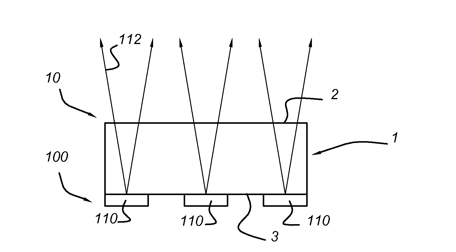
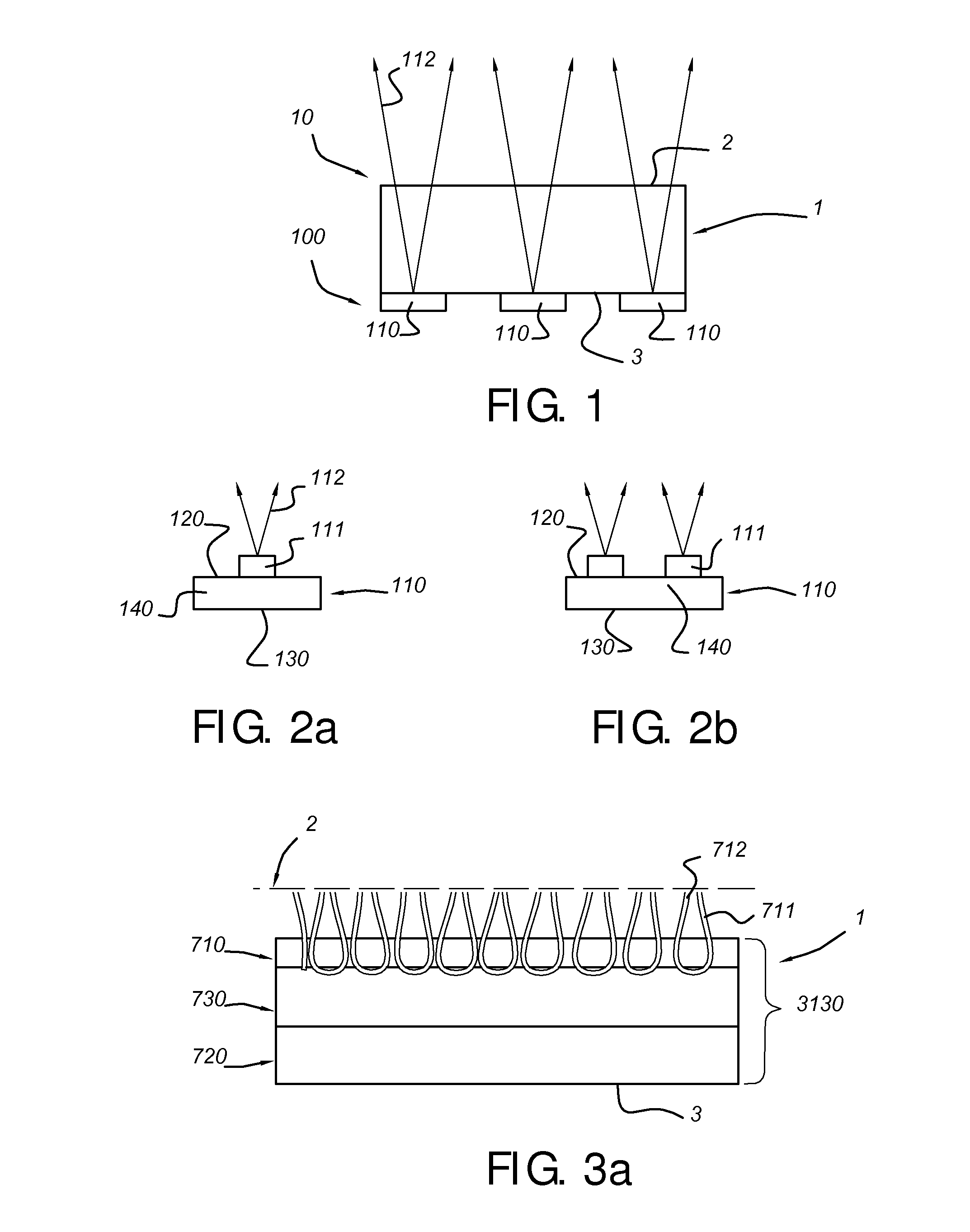
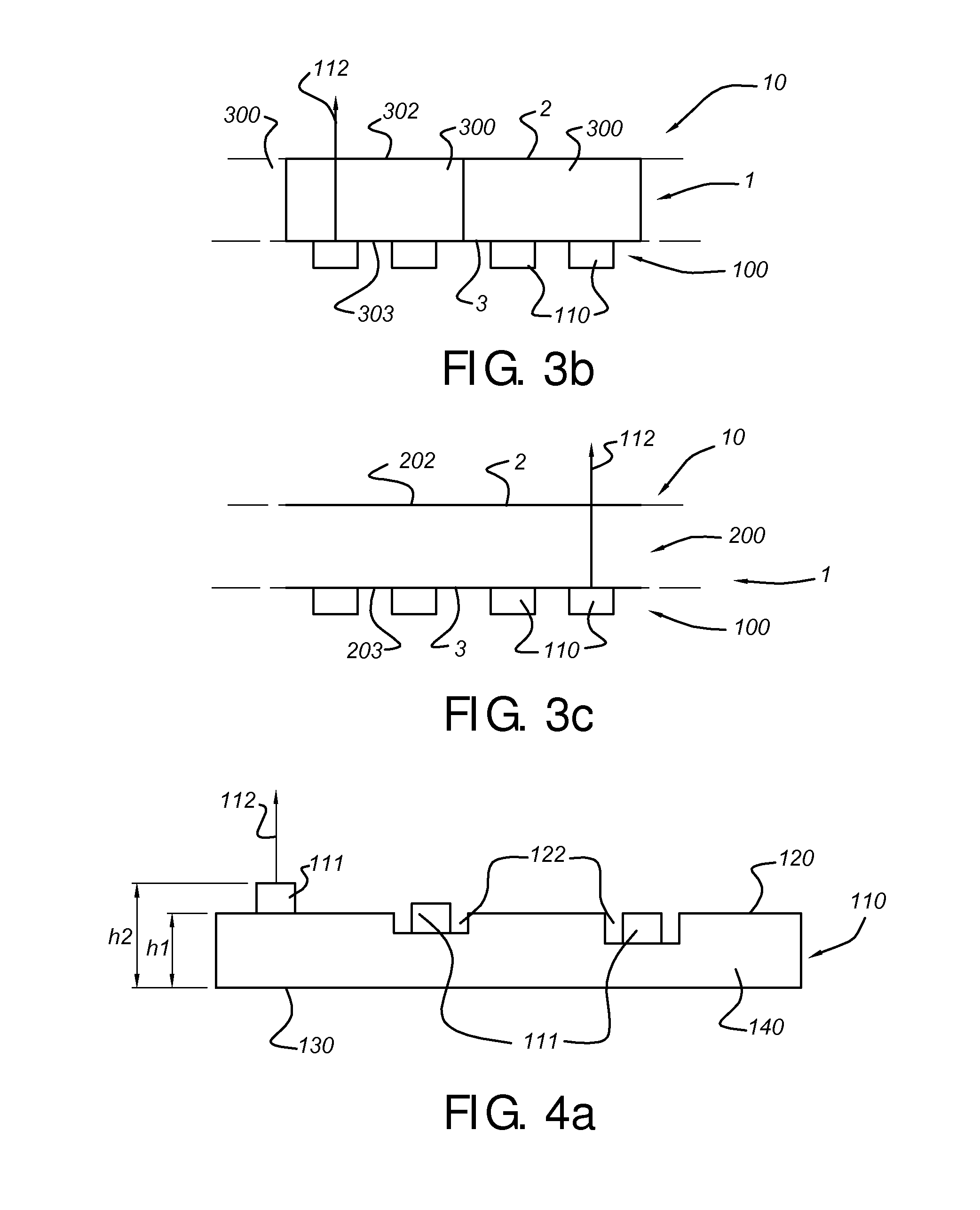
[0118]FIG. 1 schematically depicts a carpet unit 1, such as a carpet, a carpet tile, or a plurality of carpet tiles. The carpet unit has carpet unit front face 2, on which people may for instance walk, and which is in general directed to the user(s) of the carpet unit 1, and a carpet unit back side 3.

[0119]By way of example, lighting units 110 are depicted, which are, in this schematically depicted embodiment, arranged at the back side 3 of the carpet unit 1.

[0120]An advantage of arranging the lighting units at the back side 3 is that the lighting units can be separate from the carpet unit. This allows the lighting units to be re-arranged and replaced at any time in future and this also reduces the cost for the total system, because no standardized carpet+lighting combination needs to be made. In the remainder of this description we will focus on a lighting unit placed at the back side of the carpet unit, and wherein the lighting unit is separate from the carpet unit. However, it sh...


PUM

PropertyMeasurementUnit
heightaaaaaaaaaa
heightaaaaaaaaaa
temperatureaaaaaaaaaa

Abstract

The invention provides a carpet unit comprising a laminate of a tufted primary backing layer providing a carpet unit top face, an intermediate adhesive layer, and a backing layer providing a carpet unit back face, wherein the carpet unit is selected from the group consisting a carpet and a carpet tile, wherein the carpet unit further comprises an optical sensor, arranged to generate a sensor signal, wherein, seen from carpet unit top face, the optical sensor is arranged behind the primary backing layer, and wherein the carpet unit is arranged to transmit light from the carpet unit top face to the optical sensor.

Description

FIELD OF THE INVENTION[0001]The invention relates to a carpet unit for optical applications, and to a lighting arrangement comprising the carpet unit. The invention further relates to the use of such carpet unit and lighting arrangement for specific purposes.BACKGROUND OF THE INVENTION[0002]Lighting on or in floors is known in the art. EP0323682 for instance describes an apparatus for guiding the occupants of a building along a path of travel within the building which comprises modular carpet tiles which are arranged to cover the floor of the structure, with some of the tiles being signal units having a light-transmissive, molded plastics housing positioned in an opening therein, and having light-emitting diodes positioned in the housing. The light-emitting diodes are energized via an electrical cable, and thereby provide a visually discernable pathway on the floor.[0003]US20070037462 describes a method for manufacturing a distributed optical fibers scrim comprising functional optic...

Claims


Application Information

Patent Timeline
Patent Type & Authority Applications(United States)
IPC IPC(8): H05B37/02H01J40/14
CPCB64C2027/8236B64D2011/0038D05C17/02F21V23/0442D06N2209/08G02B6/3612D06N2203/041D06N7/0073D06N7/0071F21V33/006B60Q3/60B60N3/042
Inventor VANHERPEN, MAARTEN MARINUS JOHANNES WILHELMUS
Owner KONINKLIJKE PHILIPS ELECTRONICS NV
Why Eureka
Try Eureka