Velocity measuring system

a velocity measurement and velocity technology, applied in the direction of liquid/fluent solid measurement, using reradiation, instruments, etc., can solve the problems of inaccurateness and disadvantages of the technique, and achieve the effect of improving detection

Active Publication Date: 2011-11-24
TELEDYNE
View PDF2 Cites 30 Cited by
  • Summary
  • Abstract
  • Description
  • Claims
  • Application Information

AI Technical Summary

Benefits of technology

[0008]A novel apparatus for remotely measuring the direction and flow rate of liquid in an open channel flow with high resolution and precision.
[0042]To avoid prolonged mode-hop laser instabilities, which arise from slow changes in the temperature of the laser diode, from preventing data collection, in one embodiment the microprocessor causes power to be applied to the laser diode only for short periods of time during which beat signal measurements are taken. Immediately after the laser diode is turned on its temperature changes rapidly for several seconds. During this time the laser tunes rapidly through several stable and unstable operating regions. During analysis data collected during stable operation is processed while that taken during unstable operation is discarded. An added benefit of turning on the laser diode for short periods of time is that it reduces the duty cycle for sensor operation, thereby increasing power efficiency and yielding longer battery lifetimes in remote sensor operations. An alternate method of operation places a small heater band around the laser diode package to shift the temperature of the diode to a stable operating point where it can be maintained without significantly compromising power efficiency.

Problems solved by technology

This technique has the disadvantages of being inaccurate under some circumstances due to the difficulty in accurately arriving at the mean flow velocity from the surface velocity, and of detecting a signal when there are few suitable reflectors on the surface.

Method used


Image

  • Velocity measuring system
  • Velocity measuring system
  • Velocity measuring system

Examples


Embodiment Construction

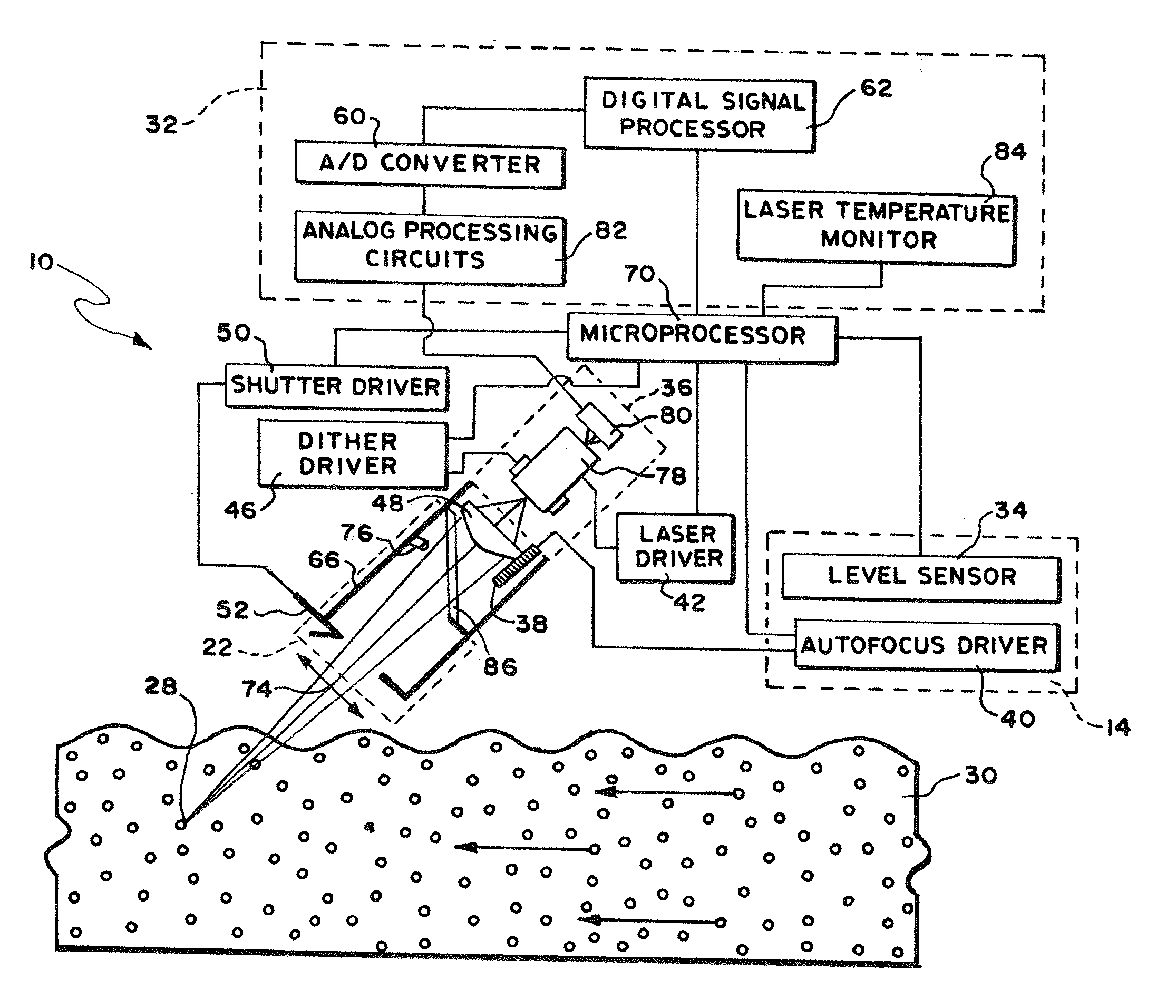
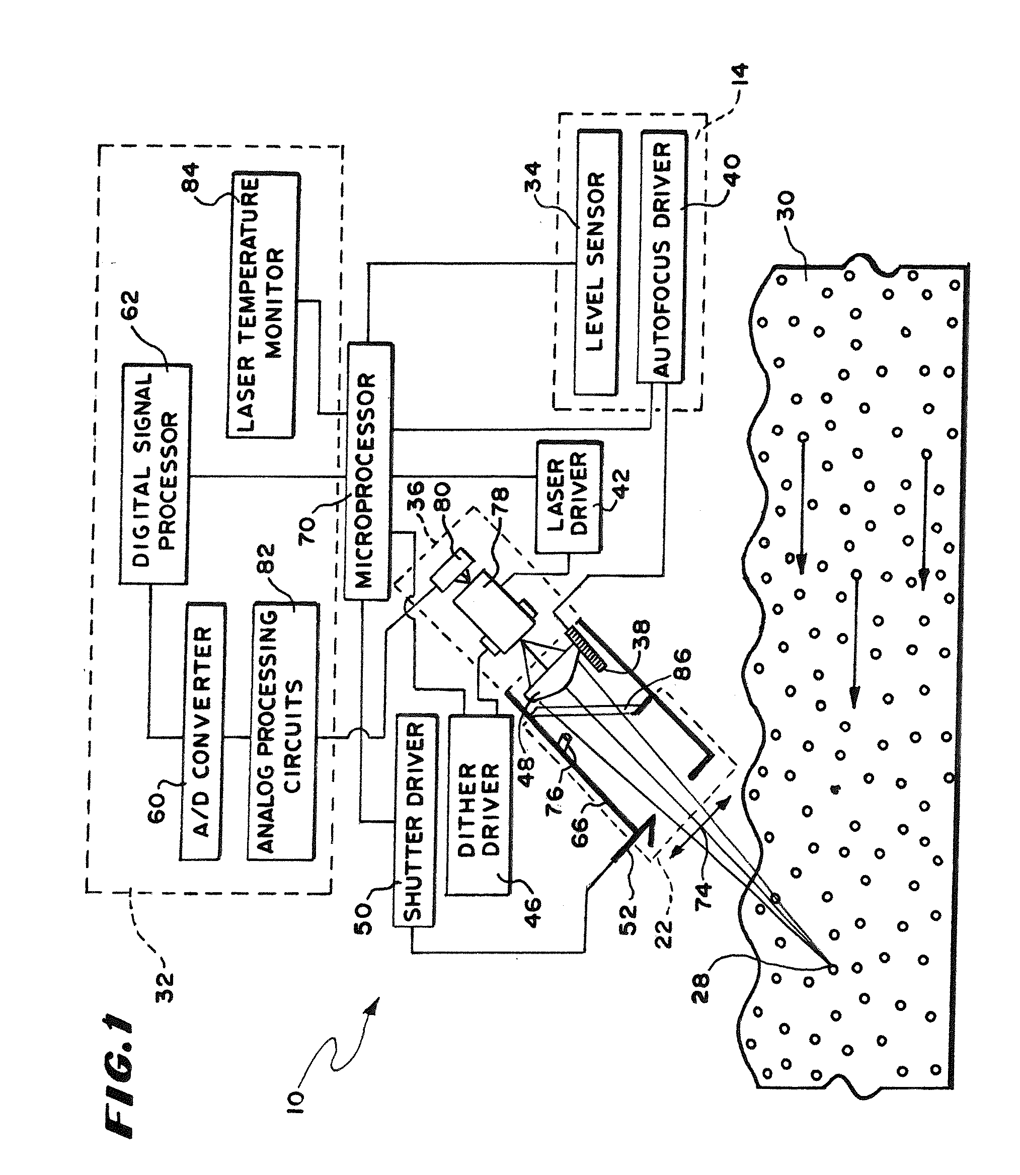
[0066]In FIG. 1, is shown a schematic block diagram of a flow meter for remotely measuring the average velocity of an open channel flow, 30. In this specification the words “open channel flow”, “flow”, “liquid flow”, “rate of flow” and “flowing steam” are used from time to time to designate the medium for which the flow meter is used. These words are not intended to be words of limitation as to the nature of the liquid, the rate of which is being measured, and the novel flow meter and are interchangeable when designating the medium characteristics of which are being measured. The flow meter 10 includes as its principal parts a Doppler beat frequency subsystem 32, a laser diode module 36, a microprocessor subsystem and input / output devices 70, a laser temperature and flow stream level monitoring system 14, and a environmental protection system 22. The flow meter uses a laser diode module 36, that contains a laser diode emitter 78 and a photodetector 80 mounted behind the rear facet o...


PUM


Abstract

A laser Doppler velocimeter uses self-mixing amplification of backreflections from scatterers below the surface of a flow.A time domain signal is divided into segments that are roughly equal to a transit time of particles through a focus of a laser beam. The segments are connected to a frequency domain through the use of an FFT algorithm to produce frequency domain data segments. Signal-to-noise ratio is enhanced through signal processing techniques using the segments to produce a final enhanced signal spectrum.

Description

BACKGROUND OF THE INVENTION[0001]This invention relates to methods and apparatuses for measuring the average velocity of an open channel flow using electromagnetic radiation such as, for example, laser signals to determine velocity by Doppler shift techniques without physically contacting the flow but measuring the flow below the surface.[0002]In one class of Doppler shift remote sensing of the velocity of an open channel flow, a laser beam is transmitted to a flow from above and the backscatter received from scatterers in the fluid such as bubbles, solid objects (e.g. debris) or microscopic particles (e.g. colloid) causing turbidity, carried by the flow are sensed. The Doppler shift in frequency between the transmitted signal and the returned signal is used to determine the velocity of the portion of the flow sampled by the laser beam. In one embodiment, the average volumetric flow rate of the sample is determined by combining the average velocity of the flow stream measured by the...

Claims


Application Information

Patent Timeline
Patent Type & Authority Applications(United States)
IPC IPC(8): G01F1/00
CPCG01P5/26G01S7/4812G01S7/4916G01S2007/4977G01S7/497G01S17/58G01S7/493
Inventor CHRISTIAN, WIILIAM R.DELCHER, RAY C.CHEN, TONGKHOSHNEVISAN, MOHSENLIESCHESKI, PHILLIP B.METCALF, MICHAEL A.
Owner TELEDYNE
Why Eureka
Try Eureka