
Internal jacket leg cutter and method

a cutter and jacket leg technology, applied in the field of internal jacket leg cutters and methods, can solve the problems of requiring the extra step of digging the trench, affecting the operation of the cutter, so as to reduce the rotational feed rate, and reduce the resistance of the cutter

Active Publication Date: 2011-12-01
AES EOT EQUIP HLDG LLC
View PDF9 Cites 13 Cited by
  • Summary
  • Abstract
  • Description
  • Claims
  • Application Information

AI Technical Summary

Benefits of technology

"The patent describes an improved method and apparatus for removing tubular members, such as caisson / jacket legs, from a seabed. The apparatus includes a frame with upper and lower end portions, and upper and lower spacing assemblies that hold the frame in place as it cuts the caisson / jacket leg. The apparatus also includes a cutting mechanism with rotary cutters that make a complete cut in the caisson / jacket leg as they rotate along an arc shaped path. The method and apparatus can be used in offshore oil drilling operations to remove damaged or worn-out equipment."

Problems solved by technology

It is important to remove jacket legs below the mud line because they are a hazard to navigation.
They are also a hazard to fishing boats that employ nets, such as shrimp boats.
This prior method has the disadvantage of requiring the extra step of digging the trench, dealing with the materials removed when digging the trench, along with maintaining the stability of such trench during cutting of the caisson / jacket leg.
If stability of the trench is not maintained, the trench can collapse during cutting operations risking bodily injury along with damage to equipment.

Method used


Image

  • Internal jacket leg cutter and method
  • Internal jacket leg cutter and method
  • Internal jacket leg cutter and method

Examples


Embodiment Construction

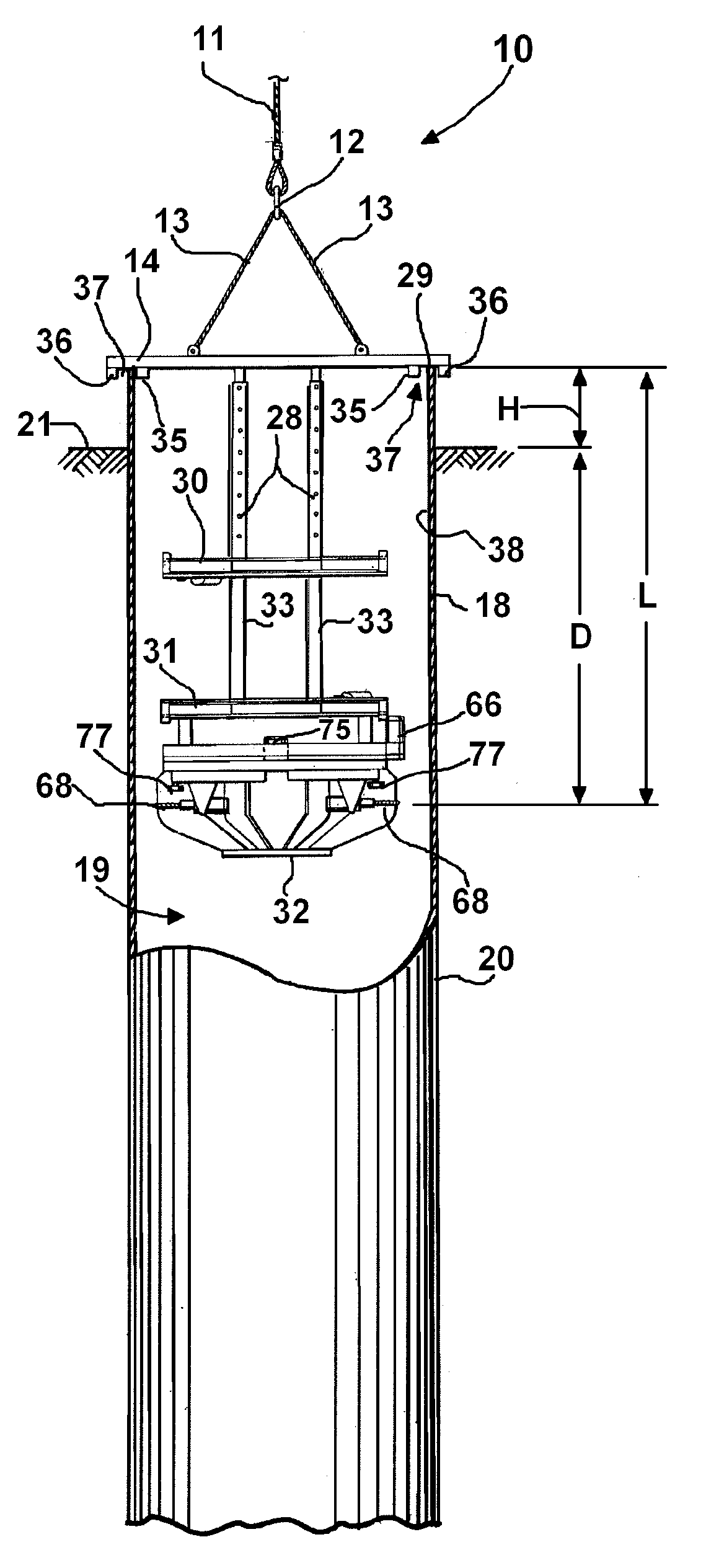
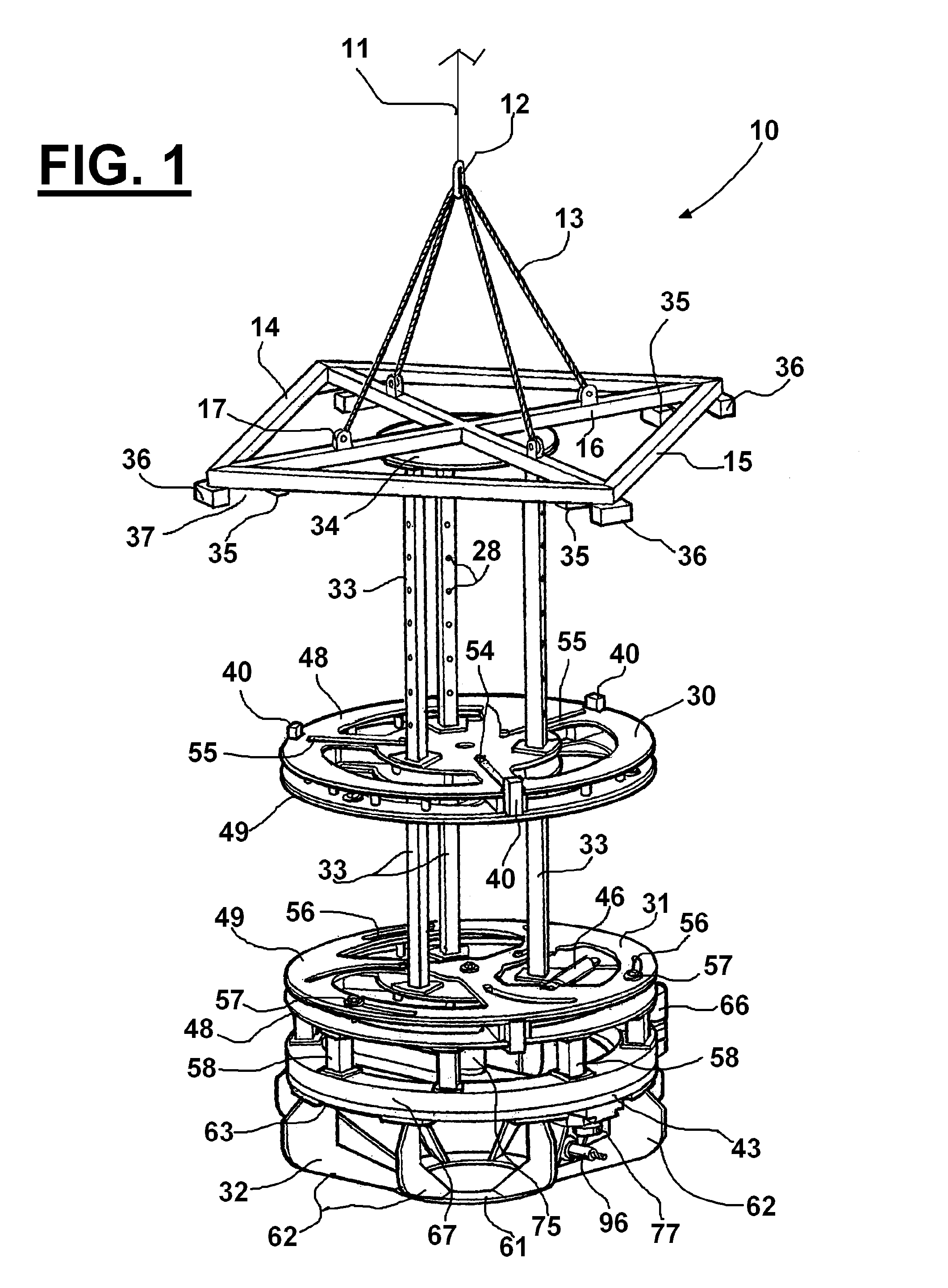
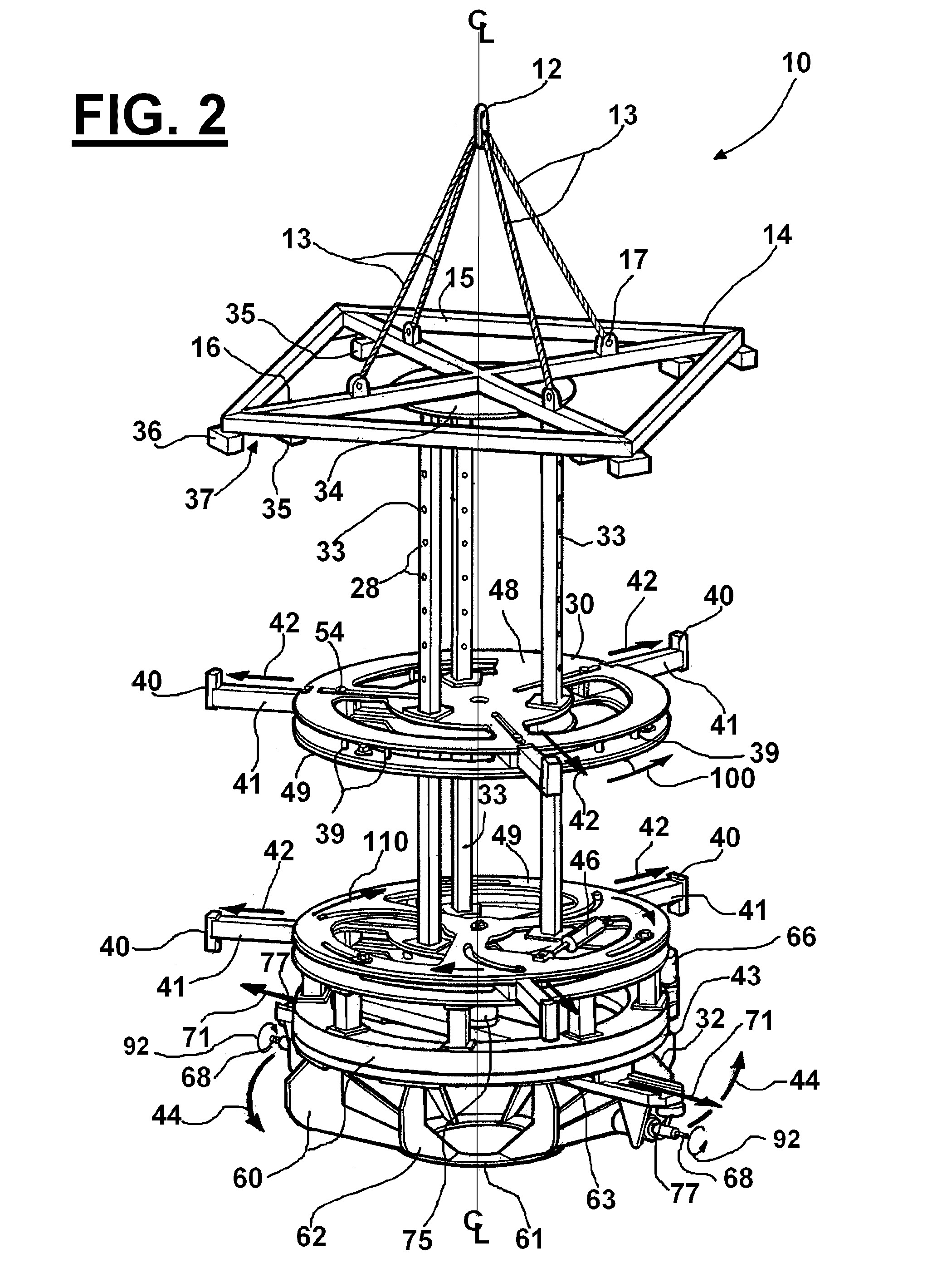
[0051]FIGS. 1-2 show the preferred embodiment of the apparatus of the present invention, designated generally by the numeral 10. FIG. 1 is an overall perspective view of one embodiment of an internal caisson / jacket leg cutter apparatus 10. FIG. 2 shows the cutter 10 schematically indicating extension of the upper and lower sets of stabilizing arms (schematically indicated by arrows 42); rotation of the positioning ring 32 in a horizontal plane also rotating the double milling cutters 68 (schematically indicated by arrows 44); extension of the double milling cutters 68 (schematically indicated by arrows 71); and rotation of the milling bits in the double milling cutters (schematically indicated by arrows 92).

[0052]Internal caisson / jacket leg cutter apparatus 10 can be lifted and lowered using a lift line 11 (e.g. crane lifting line) and rigging that can include a lifting ring 12 or like fitting and cables or slings 13 (such as shown in FIG. 6).

[0053]The internal caisson / jacket leg cu...


PUM

PropertyMeasurementUnit
depth of cutaaaaaaaaaa
stabilityaaaaaaaaaa
resistanceaaaaaaaaaa

Abstract

An internal caisson / jacket leg cutter and method provides a frame having upper and lower end portions. The upper end portion has rigging that enables the frame to be lifted. Extensible arms are movably supported upon the frame. The arms extend and retract along generally radially extending lines. Extension of the arms enables them to contact the inside surface of a caisson / jacket leg and thus center and anchor the frame within the caisson / jacket leg interior. A cutting mechanism at the lower end portion of the frame includes one or more rotary cutters or milling devices that cut the caisson / jacket leg wall as these cutters traverse an arc shaped path, tracking the caisson / jacket leg wall.

Description

CROSS-REFERENCE TO RELATED APPLICATIONS[0001]This is a continuation of International Patent Application Serial No. PCT / US2010 / 020856, filed Jan. 13, 2010, which application was a non-provisional of U.S. Provisional Patent Application Ser. No. 61 / 144,268, filed Jan. 13, 2009. Each of these applications are incorporated herein by reference. Priority of each of these applications is hereby claimed.STATEMENT REGARDING FEDERALLY SPONSORED RESEARCH OR DEVELOPMENT[0002]Not applicableREFERENCE TO A “MICROFICHE APPENDIX”[0003]Not applicableBACKGROUND[0004]Offshore marine platforms are often constructed for the purpose of producing oil and / or gas from a formation below a seabed. These offshore marine platforms typically employ an undersea structure referred to as a “jacket”. Patents have issued that are directed to platform jackets. One example is U.S. Pat. No. 4,721,416 entitled “Submersible Offshore Drilling and Production Platform Jacket” issued to Garcia. U.S. Pat. No. 4,721,416 is incorp...

Claims


Application Information

Patent Timeline
Patent Type & Authority Applications(United States)
IPC IPC(8): E02D9/04B26D3/16B23D21/14
CPCE02D9/04E02D9/005B23D21/14Y10T83/0596Y10T83/384Y10T83/391Y10T409/303808Y10T409/304424Y10T409/30644
Inventor CLARK, II, GALEN R.MARTIN, MICHAEL TODDSIEMS, GARY L.
Owner AES EOT EQUIP HLDG LLC
Learn More