

Brake Lining Assembly
a technology of brake lining and assembly, which is applied in the direction of friction lining, axially engaging brakes, brake types, etc., to achieve the effect of preventing undesirable noise emissions and being easy and economical to manufactur
- Summary
- Abstract
- Description
- Claims
- Application Information
AI Technical Summary
Benefits of technology
Problems solved by technology
Method used
Image

Examples
first embodiment
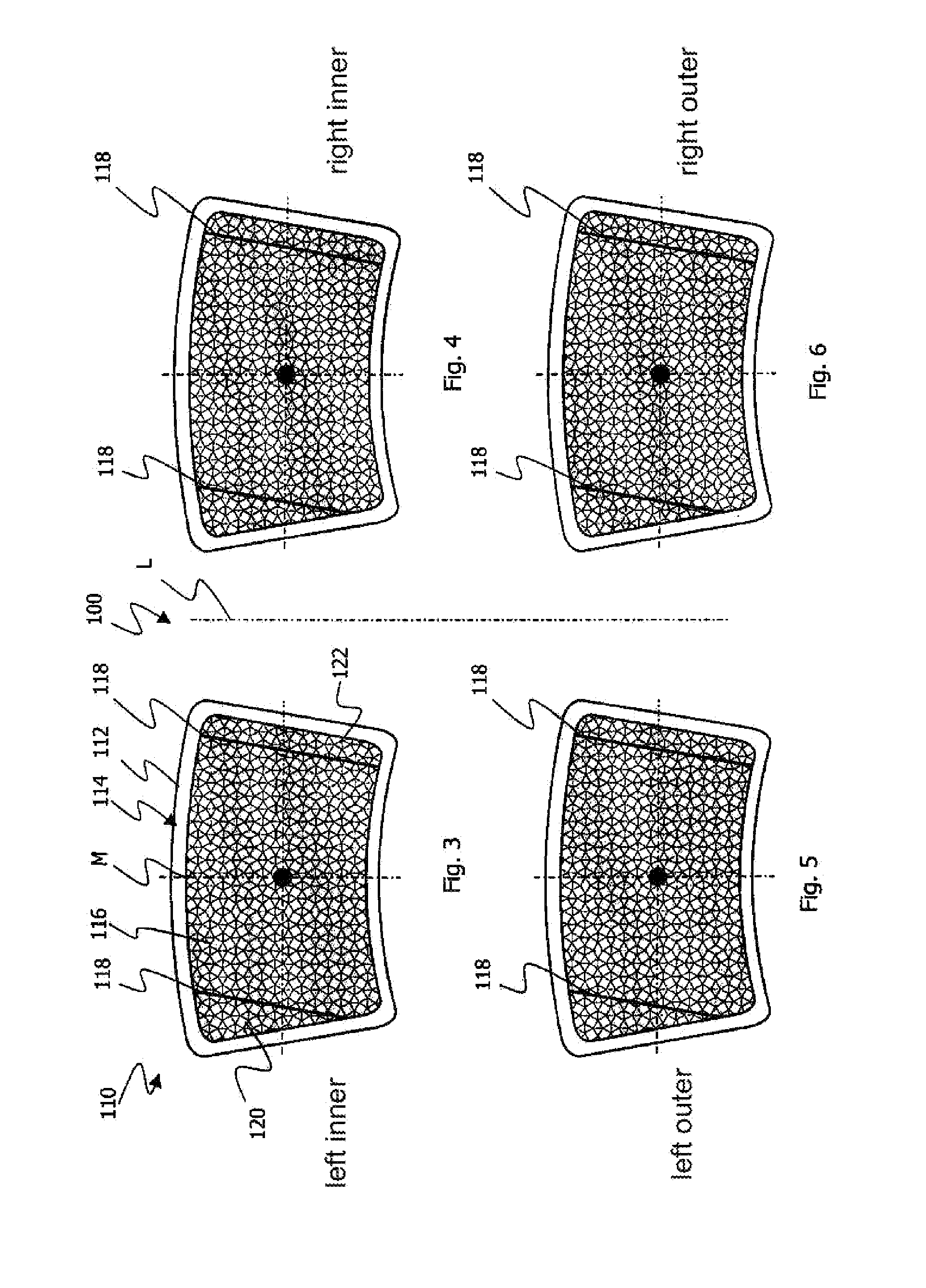
[0038]There now follows a description of various embodiments of the invention with reference to the further figures. To avoid repetition and simplify the description, for components of an identical effect or type the same reference characters as in the first embodiment are used, only prefixed by a consecutive number. To maintain the clarity of representation, in each case only one figure of an embodiment is provided completely with reference characters.
[0039]FIGS. 3 to 6 show a first embodiment of a brake system 100 having at least two brake disks (not shown here), each comprising two brake pad arrangements 110, which are disposed parallel to a brake disk that is rotatable about an axis of rotation and lie opposite one another facing the brake disk. For better pictorialization a vehicle longitudinal axis L is diagrammatically represented. FIGS. 3 and 5 show the brake pad arrangements 110 that come into operation on the left of the vehicle longitudinal axis L. In a corresponding mann...
second embodiment
[0042]FIGS. 7 to 10 show a brake system 200 according to the invention. As is evident from FIGS. 7 to 10, unlike the embodiment according to FIGS. 3 to 6 the brake pad arrangements 210 are not all of an identical design. Here, in each case the inner brake pad arrangements 210 according to FIGS. 7 and 8 and the outer brake pad arrangements 210 according to FIGS. 9 and 10 are identical to one another. Furthermore, the contour edges 218 of the inner and outer brake pad arrangements 210 have the same orientation in relation to the vehicle longitudinal axis L. Looking at the individual brake pad arrangements 210 on the left and right side of the vehicle longitudinal axis L it is apparent that in the fitted state of the brake pad arrangements 210, in a projection directed along the axis of rotation of a brake disk (not shown), the contour edges 218 of the inner and outer brake pad arrangements 210 extend substantially parallel and according to this embodiment in coincidence. The identical...
third embodiment
[0043]FIGS. 11 to 14 show a brake system 300 according to the invention having at least two brake disks. It is evident from FIGS. 11 and 12 as well as FIGS. 13 and 14 that the inner brake pad arrangements 310 according to FIGS. 11 and 12 are designed differently in relation to the vehicle longitudinal axis L. What is more, the outer brake pad arrangements 310 according to FIGS. 13 and 14 differ from one another. From a comparison of the brake pad arrangements 310 on the right of the vehicle longitudinal axis L it is evident that these are of an identical design to one another, as are the brake pad arrangements 310 on the left of the vehicle longitudinal axis L. In a projection directed along the axis of rotation of a brake disk (not shown), the contour edges 318 of the inner and outer brake pad arrangements 310 intersect in the fitted state.
[0044]It is evident from FIGS. 11 to 14 that the contour edges 318 of the brake pad arrangements 310 on the left and on the right of the vehicle...
PUM
 Abstract
Description
Claims
Application Information