Aircraft including an undercarriage motor

a technology of undercarriage motor and aircraft, which is applied in the field of aircraft, can solve the problems so as to achieve the effect of increasing the weight of the aircra

Active Publication Date: 2011-12-01
AIRBUS OPERATIONS (SAS) +1
View PDF14 Cites 31 Cited by
  • Summary
  • Abstract
  • Description
  • Claims
  • Application Information

AI Technical Summary

Benefits of technology

[0016]When the weight of the aircraft is far enough away from its maximum authorized weight, then the thrust from the engines, e.g. while idling, generally suffices to enable the aircraft to accelerate continuously. Under such circumstances, the pilot is conventionally obliged to use the brakes in order to control taxiing speed. That gives rise to premature wear of the brakes, a phenomenon that is particularly harmful for carbon brakes where wear stems mainly from the number of times the brakes are applied, as opposed to the amount of energy they dissipate. Because of that characteristic, the motors can be used as generators so as to perform a braking function holding back the aircraft to a certain speed as selected by the pilot. In this way, speed remains constant and the pilot does not need to apply several series of braking operations using the members that are dedicated for this function, thereby limiting the amount of wear they suffer. The energy absorbed by the motors may be dissipated, or better it may be used for powering the aircraft electricity network, the motor then also acting as an electricity generator.
[0036]Preferably, the aircraft is caused to taxi solely under drive from means situated on board the aircraft. This avoids any need for an external tractor vehicle.

Problems solved by technology

Nevertheless, such devices are complex and require fuel or compressed air to be delivered to the undercarriage, thereby adding pipework and thus likely to give rise to additional weight and manufacturing costs for the aircraft.
An important part of the saving in fuel consumption is then lost as a result of the additional weight.
Furthermore, conveying that amount of electrical power to the undercarriage requires a dedicated power line to be installed, thereby contributing to making the design of the aircraft more complex and increasing its weight.
Another drawback of that solution relates to delivering hydraulic or electrical power to the systems needed for an aircraft that is taxiing and preparing for flight.
Nowadays, the APU is not designed to be capable nominally, of powering all of the needs of the airplane.
However that also leads to the aircraft being made significantly more complex and heavier.
However that method raises operational difficulties that are difficult for an airline to accept.

Method used


Image

  • Aircraft including an undercarriage motor
  • Aircraft including an undercarriage motor
  • Aircraft including an undercarriage motor

Examples


Embodiment Construction

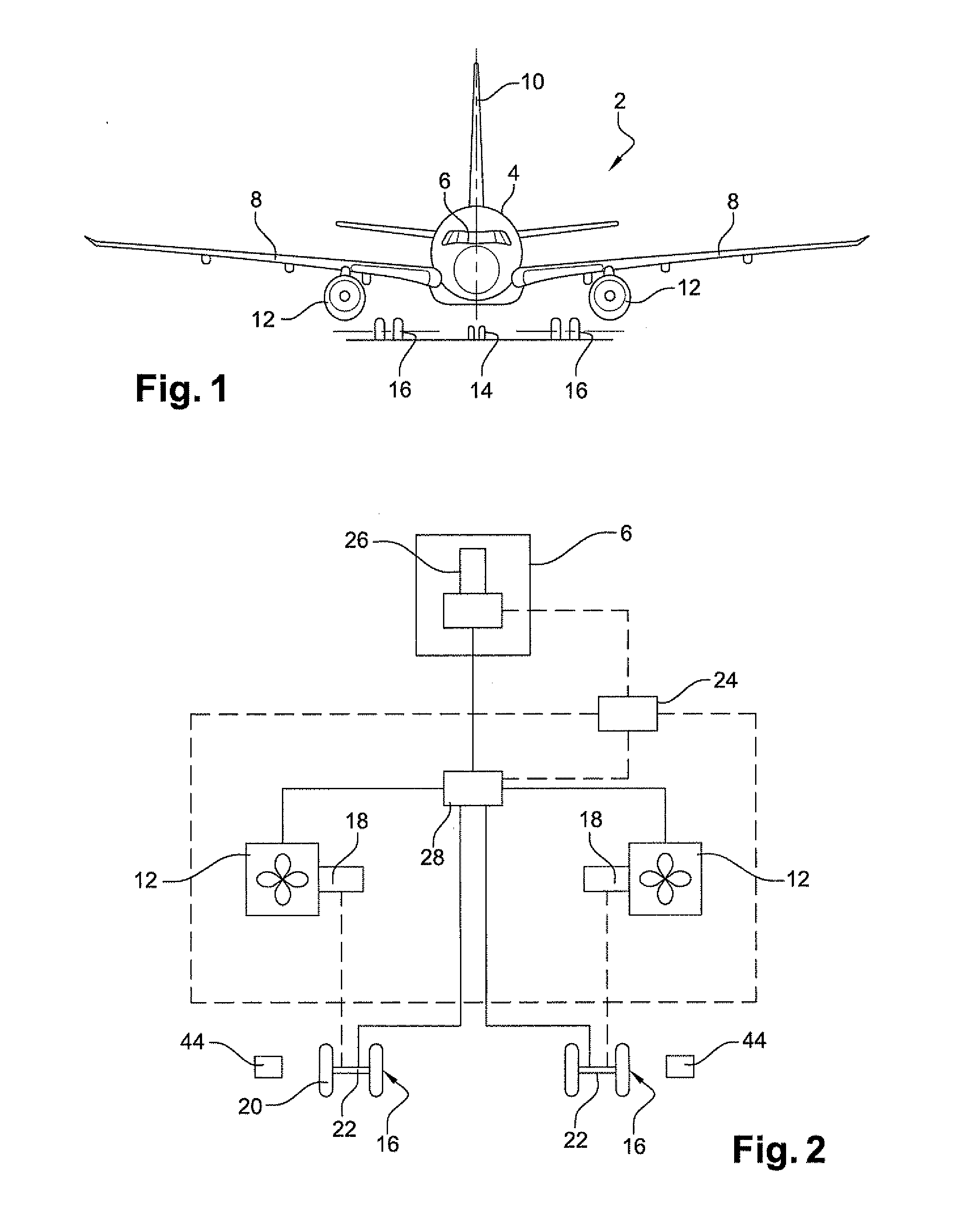
[0045]A first embodiment of an aircraft 2 of the invention is shown in FIGS. 1 and 2.

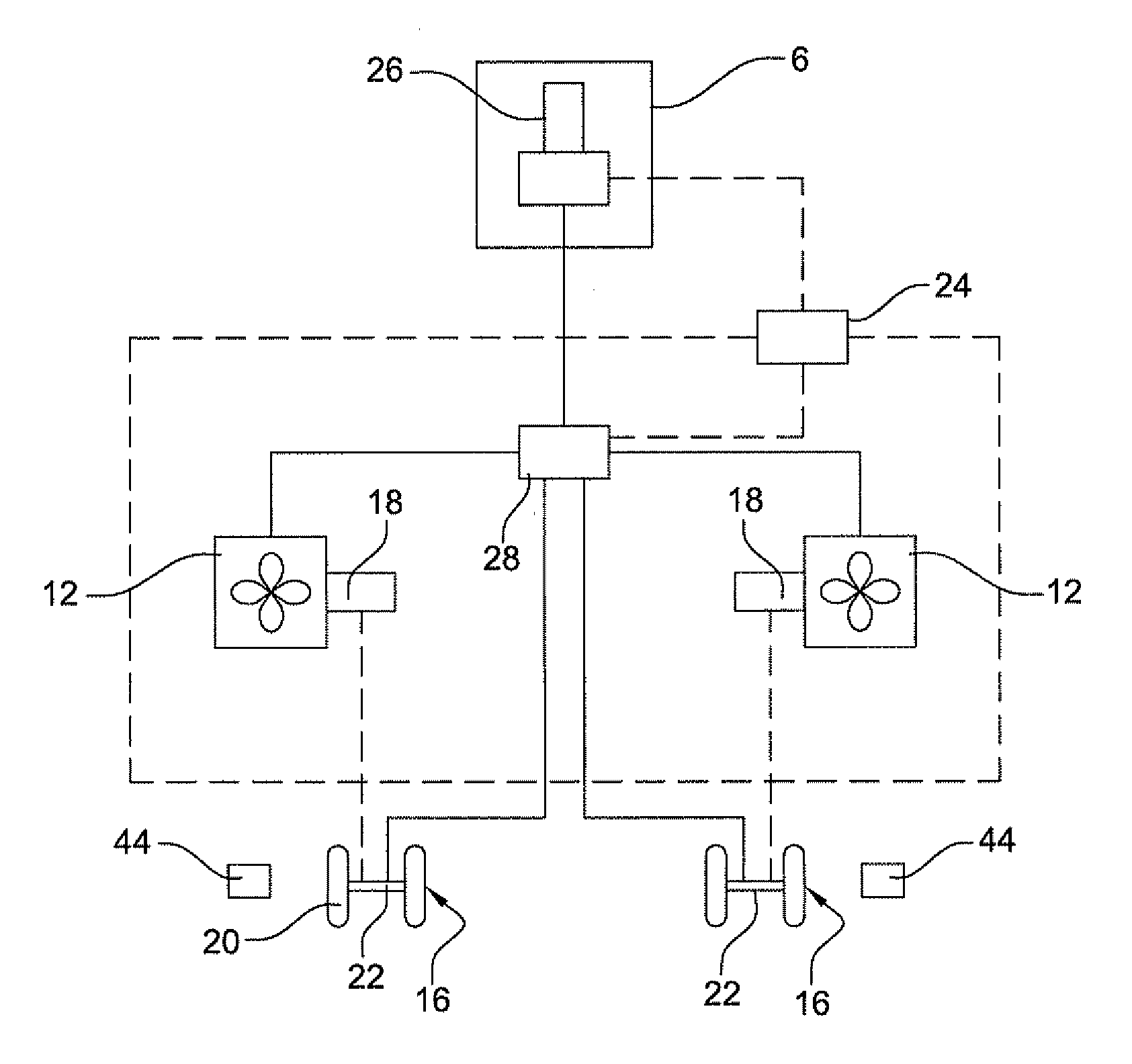
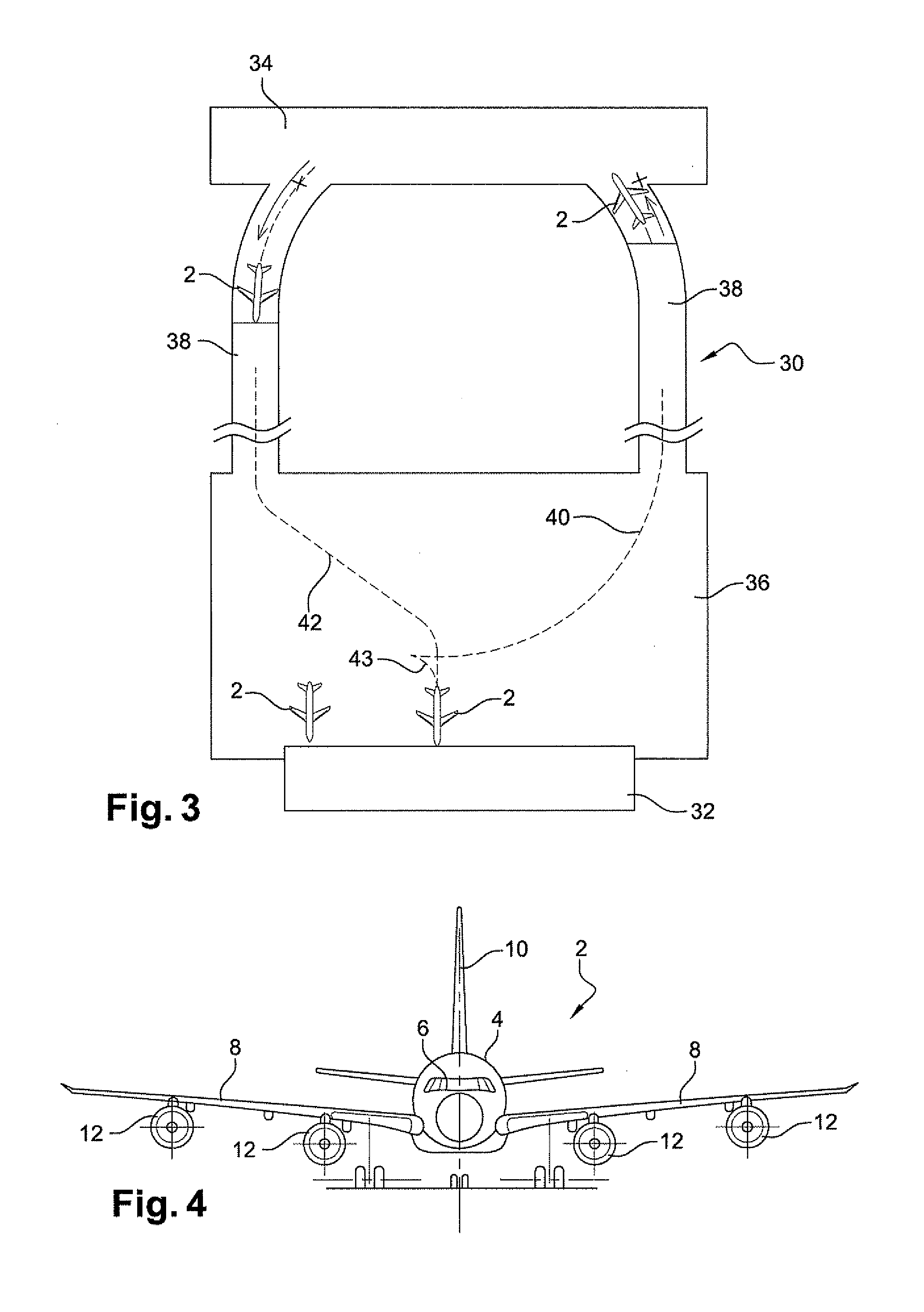
[0046]In this example the aircraft 2 is an aerodyne, and specifically an airplane. More specifically it is a commercial airliner for transporting freight and / or passengers. It is suitable for receiving at least one person. It has a fuselage 4 with a cockpit 6 of the airplane at the front thereof. It has two wings 8 extending on either side of the fuselage together with a tail fin 10. The airplane 2 has two engines 12 carried by respective ones of the wings 8 for propelling the airplane in flight. By way of example they may be turbojets or turboprops. The engines 12 operate by burning a fuel such as kerosene coming from tanks (not shown) of the airplane. Each engine 12 is associated with an electricity generator 18 having a rotary portion that is suitable for being driven by the engine in order to produce electricity.

[0047]The airplane has undercarriages comprising a nosewheel 14 situated under the f...


PUM


Abstract

The aircraft includes at least one engine suitable for propelling the aircraft in flight, at least one motor of an undercarriage, and automatic means arranged to cause the aircraft to taxi under drive directly from the engine, while simultaneously using the motor for taxiing, other than during takeoff or landing.

Description

FIELD OF THE INVENTION[0001]The invention relates to aircraft, and in particular to their movements on the ground, specifically to taxiing between a takeoff and landing runway and a parking point in the vicinity of a terminal.[0002]In conventional manner, while moving on the ground, aircraft either make use of their engines, or they are towed by vehicles, which transmit thrust to them via an undercarriage. This applies in particular to commercial aircraft using turbojets or turboprops as their engines. However using engines for taxiing gives rise to significant levels of fuel consumption and associated pollution. Having recourse to a specialized tractor vehicle limits the independence of the aircraft when moving on the ground.BACKGROUND OF THE INVENTION[0003]Proposals are made, in particular in documents FR-2 930 759 and FR-2 930 760, to place motors in association with certain undercarriages so as to enable aircraft to taxi under their own power. Such a motor may be constituted, fo...

Claims


Application Information

Patent Timeline
Patent Type & Authority Applications(United States)
IPC IPC(8): B64C25/50B64C25/42
CPCY02T50/823B64C25/405Y02T50/80
Inventor CROS, CHRISTOPHEBROUSSE, PIERRE HENRIBEDARRIDES, JEREMY
Owner AIRBUS OPERATIONS (SAS)
Why Eureka
Try Eureka