Signal transmission system and signal transmission method

Inactive Publication Date: 2011-12-01
NEC CORP
View PDF2 Cites 18 Cited by
  • Summary
  • Abstract
  • Description
  • Claims
  • Application Information

AI Technical Summary

Benefits of technology

[0016]A signal transmission system and a signal transmission method of the present invention aim to reliably transfer signals to be transmitted and received through a plurality of data lines by using a circuit with a small number of transformers and a small circuit area.

Problems solved by technology

When signals are transmitted among a plurality of semiconductor chips having different power supply voltages, direct transmission of signals through lines causes a difference in DC voltage, which may result in damage to the semiconductor chips and failure of signal transmission.
The transfer of signals to be transmitted and received through a plurality of data signal lines via the transformers causes a problem of an increase in the area of the semiconductor chip.

Method used


Image

  • Signal transmission system and signal transmission method
  • Signal transmission system and signal transmission method
  • Signal transmission system and signal transmission method

Examples


first exemplary embodiment

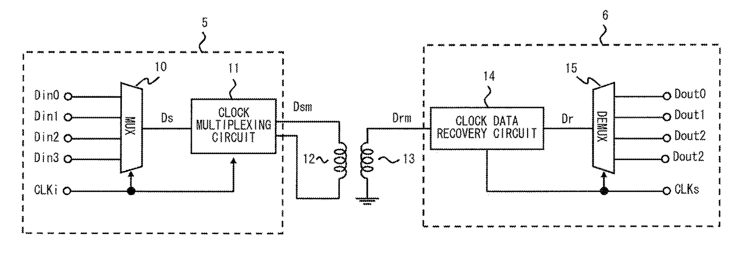
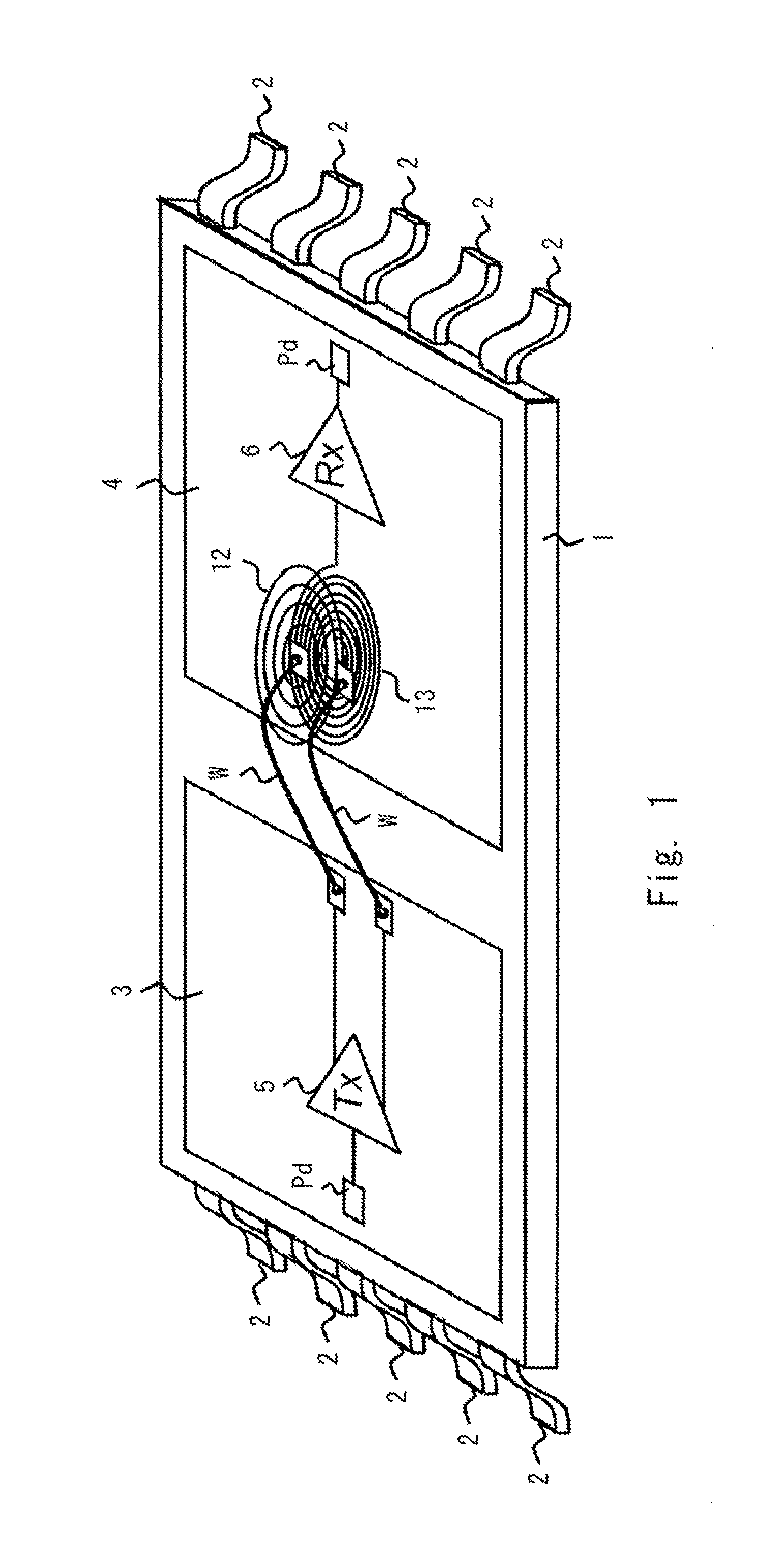
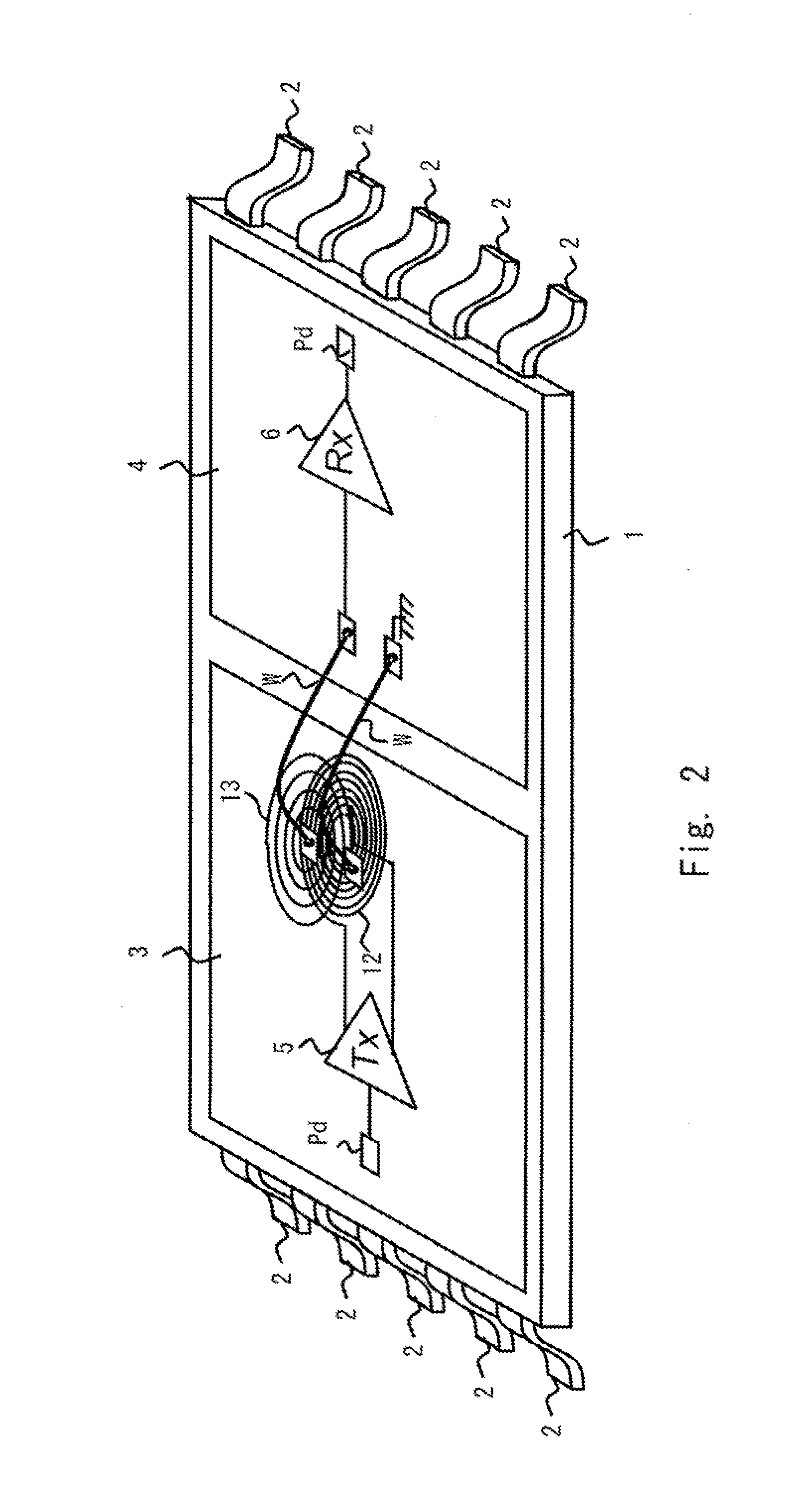
[0059]Hereinafter, exemplary embodiments of the present invention will be described with reference to the drawings. First, a method for mounting a signal transmission system according to this exemplary embodiment will be described. In the signal transmission system according to this exemplary embodiment, transformers are constituted using two coils formed on one or two semiconductor chips. In other words, the two coils function as AC coupling elements (for example, transformers) magnetically coupled together. A primary coil is connected to a transmitting node of a transmission circuit formed on the semiconductor chip, and a secondary coil is connected to a receiving node of a reception circuit. FIGS. 1 to 10 show schematic views each illustrating a mounted state of the signal transmission system according to this exemplary embodiment.

[0060]In the mounted state shown in FIG. 1, a first semiconductor chip 3 and a second semiconductor chip 4 are mounted in a semiconductor package 1. Ea...

second exemplary embodiment

[0112]A signal transmission system according to a second exemplary embodiment will be described. Hereinafter, the elements described in the signal transmission system according to the first exemplary embodiment are denoted by the same reference numerals as those used to describe the signal transmission system according to the first exemplary embodiment, and the description thereof is omitted.

[0113]First, FIGS. 27 and 28 show schematic views each illustrating a mounted state of the signal transmission system according to the second exemplary embodiment. In the mounting example shown in FIG. 27, two transformers are provided on the side of the second semiconductor chip 4. In the mounting example shown in FIG. 28, two transformers are provided on the side of the first semiconductor chip 3. The two transformers are composed of a first transformer including a first primary coil 12a and a first secondary coil 13a; and a second transformer including a second primary transformer 12b and a s...

third exemplary embodiment

[0122]A signal transmission system according to a third exemplary embodiment will be described. Hereinafter, the elements described in the signal transmission systems according to the first and second exemplary embodiments are denoted by the same reference numerals as those used to describe the signal transmission systems according to the first and second exemplary embodiments, and the description thereof is omitted.

[0123]First, FIGS. 31 and 32 show schematic views each illustrating a mounted state of the signal transmission system according to the third exemplary embodiment. In the mounting example shown in FIG. 31, the transformers in the mounting example of the signal transmission system shown in FIG. 1 are replaced with capacitors. In the mounting example shown in FIG. 32, the transformers in the mounting example of the signal transmission system shown in FIG. 27 are replaced with capacitors. That is, the signal transmission system according to the third exemplary embodiment is ...


PUM


Abstract

A signal transmission system according to the present invention includes a first data conversion circuit (10) that converts first parallel data into first serial data (Ds) according to a first clock signal (CLKi); a clock multiplexing circuit (11) that outputs to a transmitting node a transmission signal (Dsm) obtained by multiplexing the first clock signal (CLKi) with the first serial data (Ds); a clock data recovery circuit (14) that extracts second serial data (Ds) corresponding to the first serial data and a second clock signal (CLKs) corresponding to the first clock signal (CLKi) from a reception signal (Drm) received through a receiving node; and a second data conversion circuit (15) that converts the second serial data (Ds) into second parallel data according to the second clock signal (CLKs). As a result, the chip area can be reduced.

Description

TECHNICAL FIELD[0001]The present invention relates to a signal transmission system and a signal transmission method, and more particularly, to a signal transmission system and a signal transmission method for transmitting a signal through an AC coupling element.BACKGROUND ART[0002]When signals are transmitted among a plurality of semiconductor chips having different power supply voltages, direct transmission of signals through lines causes a difference in DC voltage, which may result in damage to the semiconductor chips and failure of signal transmission. Accordingly, when signals are transmitted among a plurality of semiconductor chips having different power supply voltages, the semiconductor chips are connected with an AC coupling element to transmit only AC signals. Examples of the AC coupling element include a capacitor and a transformer. Here, the transformer refers to an AC coupling element including a primary coil and a secondary coil which are magnetically coupled together. ...

Claims


Application Information

Patent Timeline
IPC IPC(8): H03K19/0175
CPCH04L7/0008H04L25/0266H01L2224/48091H01L2224/48137H01L2924/00014H01L2224/05553H01L2224/45099
Inventor KAERIYAMA, SHUNICHI
Owner NEC CORP
Why Eureka
Try Eureka