Variable-length decoding device

a decoding device and variable-length technology, applied in the field of variable-length decoding devices, can solve the problems of increasing the number of consecutive zero values among coefficients after orthogonal transformation, consuming an information register area, and invalid data located at a data buffer address corresponding to a zero value, so as to reduce power consumption and read data power consumption, the effect of improving efficiency

Inactive Publication Date: 2011-12-01
PANASONIC CORP
View PDF2 Cites 10 Cited by
  • Summary
  • Abstract
  • Description
  • Claims
  • Application Information

AI Technical Summary

Benefits of technology

[0037]Here, the end determination unit may be further configured to issue a request to the flag buffer control unit for stop of updating, when the number of components output from the selecting unit reaches the number of component values from the component value at the beginning of the block up to the last component value in the block, and the flag buffer control unit may be configured to stop updating a flag buffer read pointer of the flag buffer for reading of the component values following the last component value in the block and output a flag of zero to the data buffer control unit, when the flag buffer control unit receives a request for stop of reading from the end determination unit. In this configuration, after component values are read up to the last component value in a block, a flag of “0” is repeatedly output for the component values from the component value following the last component value up to the component value at the end of the block. This also reduces power consumption in reading data from the flag buffer and the data buffer.
[0038]Here, the flag buffer control unit may be configured to initialize an area of the flag buffer to zero before or after decoding coded data corresponding to the block, the area corresponding to a block. In this configuration, the process of setting “0” for each zero component value is saved by zero-clearing the flag buffer in advance, so that power consumption is further reduced.
[0039]Here, the variable-length decoding device may further include a free space managing unit configured to manage free space in the data buffer and free space in the flag buffer, and issue a request to the variable-length decoding unit for stop of decoding or a permission to the variable-length decoding unit to decode a following block, depending on the free space in the data buffer and the free space in the flag buffer. In this configuration, the flag buffer does not hold flags for component values from the component value following the last component value to the component value at the end of the block, so that free space in the flag buffer and the data buffer for the components values are saved. The free space can be used for the next block for higher efficiency. In addition, variable-length decoding of the following block is moved forward so that performance of processing is increased.
[0040]Here, the free space managing unit may be configured to issue the permission to the variable-length decoding unit to decode a following block, when the data buffer and the flag buffer have free space at a time when the end determination unit determines that one of the decoded component values is the last component value. In this configuration, the free space can be used for the next block for higher efficiency. In addition, variable-length decoding of the following block is moved forward so that performance of processing is increased.

Problems solved by technology

One problem is that data located at a data buffer address corresponding to a zero value may be invalid because the address adding unit 502 determines a write location of a nonzero coefficient in the data buffer 508.
The other problem is that the number of consecutive zero values among coefficients after orthogonal transformation increases as the frequency of components increases.
In addition, consuming an area of the information register, which is a limited resource, by filling the area with “0” is inefficient.
For example, in recent years, semiconductor circuits have been required to perform complex and various video coding processes and high-resolution video processes.
However, reducing accesses for writing and reading of nonzero coefficients and improving efficiency of processes still fail to achieve sufficient reduction in power consumption or increase in efficiency.

Method used


Image

  • Variable-length decoding device
  • Variable-length decoding device
  • Variable-length decoding device

Examples


embodiment 1

[0077]The following describes Embodiment 1 of the present invention with reference to the drawings.

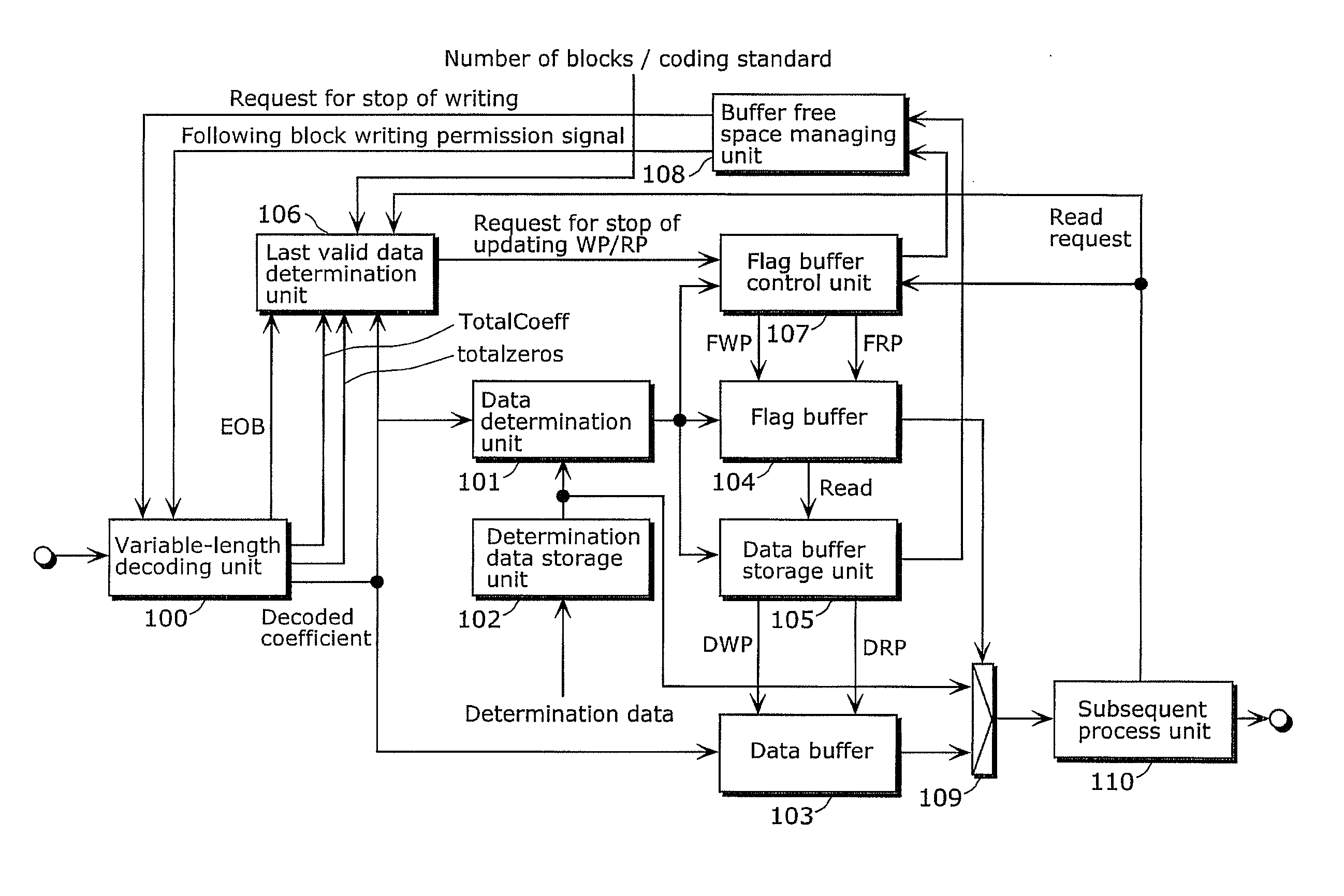
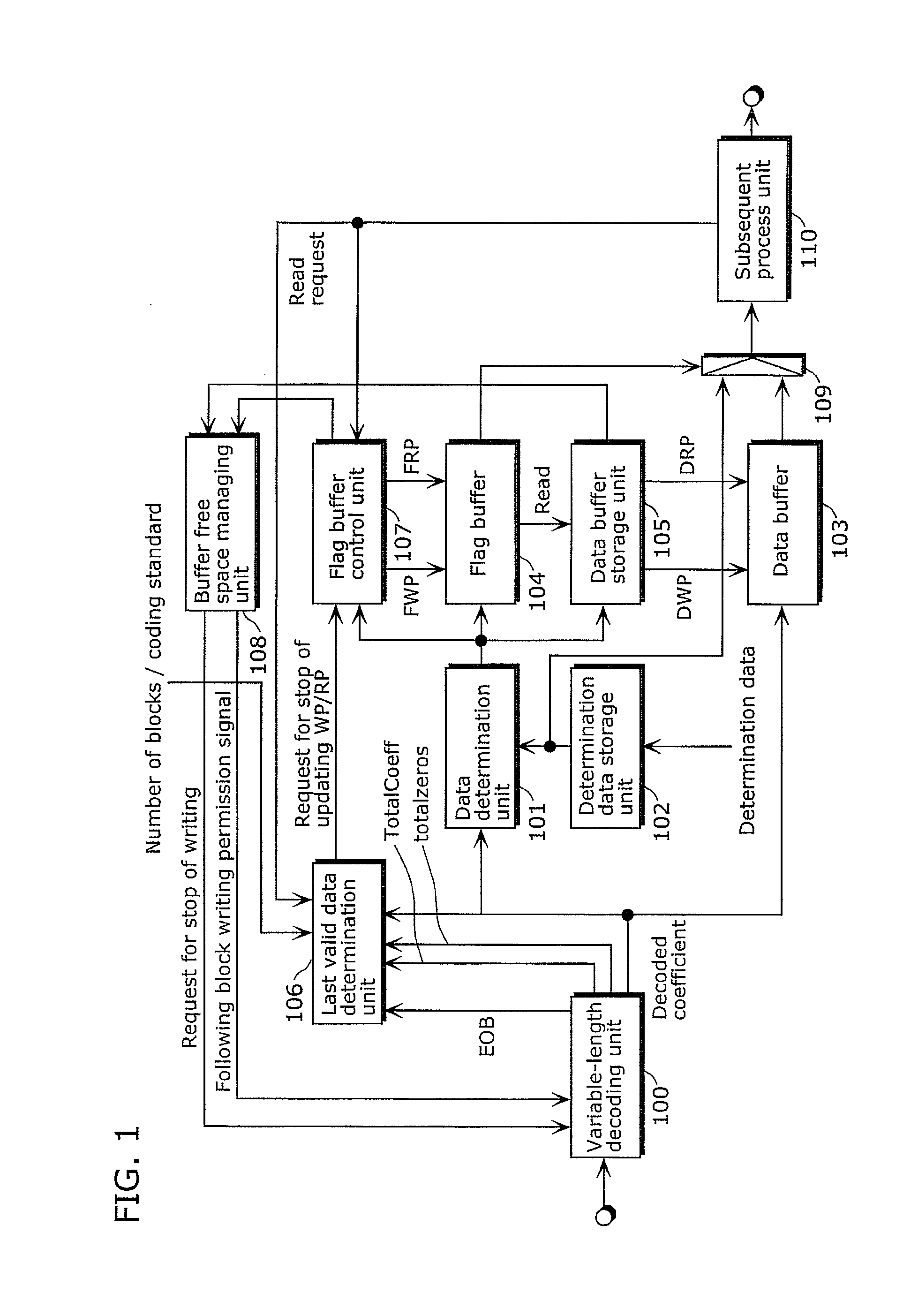
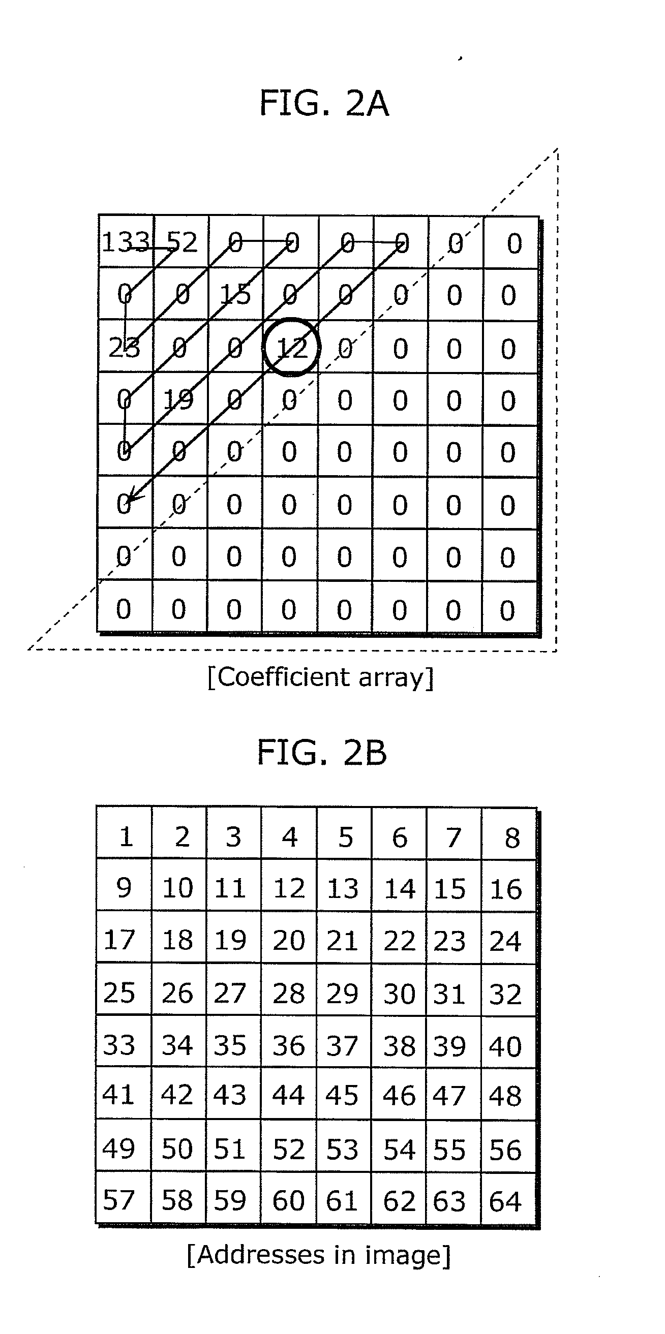
[0078]FIG. 1 shows a configuration of a variable-length decoding device according to Embodiment 1 of the present invention. In Embodiment 1, it is assumed that each block is composed of 8×8 coefficients and video data is coded in an MPEG-2 format.

[0079]Referring to FIG. 1, the variable-length decoding device includes a variable-length decoding unit 100, a data determination unit 101, a determination data storage unit 102, a data buffer 103, a flag buffer 104, a data buffer control unit 105, a last valid data determination unit 106, a flag buffer control unit 107, a buffer free space managing unit 108, a selecting unit 109, and a subsequent process unit 110.

[0080]The variable-length decoding unit 100 decodes coded data into component values (that is, coefficients).

[0081]The data determination unit 101 determines whether or not each of the decoded component values is a specific value. Th...

embodiment 2

[0102]The following describes Embodiment 2 of the present invention with reference to the drawings. The configuration according to Embodiment 2 of the present invention is shown in FIG. 1, which also shows the configuration according to Embodiment 1 of the present invention, and thus the description thereof is omitted.

[0103]A variable-length decoding device according to Embodiment 2 is different from the variable-length decoding device according to Embodiment 1 in that information of which the last valid data determination unit is notified is not EOB but TotalCoeff and totalzeros. In this configuration, as in the case where EOB is used, the number of trailing zero values can be obtained by subtracting the total number of blocks from the sum of TotalCoeff and totalzeros. Therefore, the variable-length decoding device according to Embodiment 2 produces the same effect as the variable-length decoding device according to Embodiment 1.

embodiment 3

[0104]The following describes Embodiment 3 of the present invention with reference to the drawings.

[0105]FIG. 8 shows a configuration of a variable-length decoding device according to Embodiment 3 of the present invention. In Embodiment 3, it is assumed that each block is composed of 4×4 coefficients and video data is coded in an H.264 / AVC format.

[0106]In FIG. 8, the variable-length decoding device includes a variable-length decoding unit 200, a data buffer 203, a flag buffer 204, a data buffer control unit 205, a last valid data determination unit 206, a flag buffer control unit 207, a buffer free space managing unit 208, a selecting unit 209, and a subsequent process unit210.

[0107]The variable-length decoding unit 200 detects and decodes a first code, a second code, a third code, and a fourth code, that is, TotalCoeff, totalzero, LEVEL, and run_before, respectively, from coded data. The TotalCoeff indicates the number of nonzero coefficients included in a block. The totalzero indi...


PUM


Abstract

A variable-length decoding device includes a data determination unit which determines whether or not each of component values decoded by a variable-length decoding unit is a specific value; a data buffer that holds only a component value which is not the specific value; a last valid data determination unit which determines component values other than the last one of the component values not the specific value in a block; a flag buffer which holds flags each having a corresponding component value among the component values from the component value at the beginning of the block to the last component value and indicating whether or not the corresponding component value is the specific value; a flag buffer control unit which sets the flags; a data buffer control unit which controls writing in the data buffer; and a selecting unit which selects either zero or a coefficient read from the data buffer.

Description

CROSS REFERENCE TO RELATED APPLICATION[0001]This is a continuation application of PCT application No. PCT / JP2009 / 003542 filed on Jul. 28, 2009, designating the United States of America.BACKGROUND OF THE INVENTION[0002](1) Field of the Invention[0003]The present invention relates to variable-length decoding devices which decode coded data including a variable-length code into component values composing a block, and particularly to a variable-length decoding device that performs variable-length decoding, which is a fundamental process in coding and decoding of images.[0004](2) Description of the Related Art[0005]Currently available methods of compressing and expanding videos are defined by various video coding standards, such as Moving Picture Expert Group (MPEG) including MPEG-1, MPEG-2, and MPEG-4, H.264 / AVC, and VC-1, so that the methods of compressing and expanding videos support various image sizes and media. For example, a method according to the MPEG-1 or the MPEG-2 is used for...

Claims


Application Information

Patent Timeline
Patent Type & Authority Applications(United States)
IPC IPC(8): H03M7/40
CPCH03M7/40H03M7/48H04N19/93H04N19/423H04N19/91
Inventor KUROKI, HIDEKIFURUTA, TAKESHI
Owner PANASONIC CORP
Why Eureka
Try Eureka