
Method and arrangement for a low radar cross section antenna

a cross-section antenna and low-frequency technology, applied in the direction of antennas, antenna details, protective material radiating elements, etc., can solve the problems of reducing the passive signature of aircraft sensors such as antennas, limited reason to embark on a costly rcs reduction programme of a 4g aircraft, and widespread knowledg

Active Publication Date: 2011-12-01
SAAB AB
View PDF3 Cites 7 Cited by
  • Summary
  • Abstract
  • Description
  • Claims
  • Application Information

AI Technical Summary

Benefits of technology

[0023]to solve the problem of providing an AESA with improved handling and mechanical stability while at the same time achieving a low RCS.
[0025]Electrically Scanned Antenna, AESA, with a low Radar Cross Section (RCS), comprising an AESA enclosure and at least two antenna elements. Said antenna elements being arranged to be mounted on a front surface of the AESA enclosure and embedded in a lightweight structure. The front surface and side surfaces of the AESA enclosure and the antenna elements are arranged to be covered with the lightweight structure wherein a thin laminate is arranged to cover an outer top surface and an outer side surface of the lightweight structure. Parts of the lightweight structure is further arranged to be doped with a lossy material having dielectric, magnetic and / or resistive losses, thus making these parts of the lightweight structure absorbing for electromagnetic radiation.
[0026]This object is further achieved by providing a method for arranging an antenna structure for an Active Electrically Scanned Antenna, AESA, with a low Radar Cross Section (RCS), comprising an AESA enclosure and at least two antenna elements. Said antenna elements are mounted on a front surface of the AESA enclosure and embedded in a lightweight structure. The front surface and side surfaces of the AESA enclosure and the antenna elements are covered with the lightweight structure wherein a thin laminate covers an outer top surface and an outer side surface of the lightweight structure. Parts of the lightweight structure are doped with a lossy material having dielectric, magnetic and / or resistive losses, thus making these parts of the lightweight structure absorbing for electromagnetic radiation.

Problems solved by technology

but there is often a problem with reducing the passive signature of the aircraft sensors such as antennas.
Another way to put it is that there is limited reason to embark on a costly RCS reduction programme of a 4G aircraft as long as the flat-plate remains in place.
However, it is not widely known that the RCS of an ordinary AESA is too high for any aircraft with substantial, low-RCS enabled abilities.
Most of the problems with existing stealth AESA solutions have been given unique solutions leading to high complexity, and consequently, a high cost.
In some cases the performance is also limited.
Some main problems are:Difficulties to achieve wide-band matching.Complexity is added by the introduction of absorbers for cross-polarized incident waves to an already complex antenna.
Since it needs to support itself (or to be mounted against a supporting surface) against vibrations over the large aperture, complicated mechanical problems arise, especially since the absorber needs to be slotted.A separate solution is required for absorption at the AESA side surfaces and at the base surface in order to reduce scattering adding further to the overall complexity.Diffuse scattering from the antenna aperture.The conventional hermeticity solution with a laminate cover worsens the RCS.
This leads to a thickness that result in limitations of scannability and bandwidth.

Method used


Image

  • Method and arrangement for a low radar cross section antenna
  • Method and arrangement for a low radar cross section antenna
  • Method and arrangement for a low radar cross section antenna

Examples


Embodiment Construction

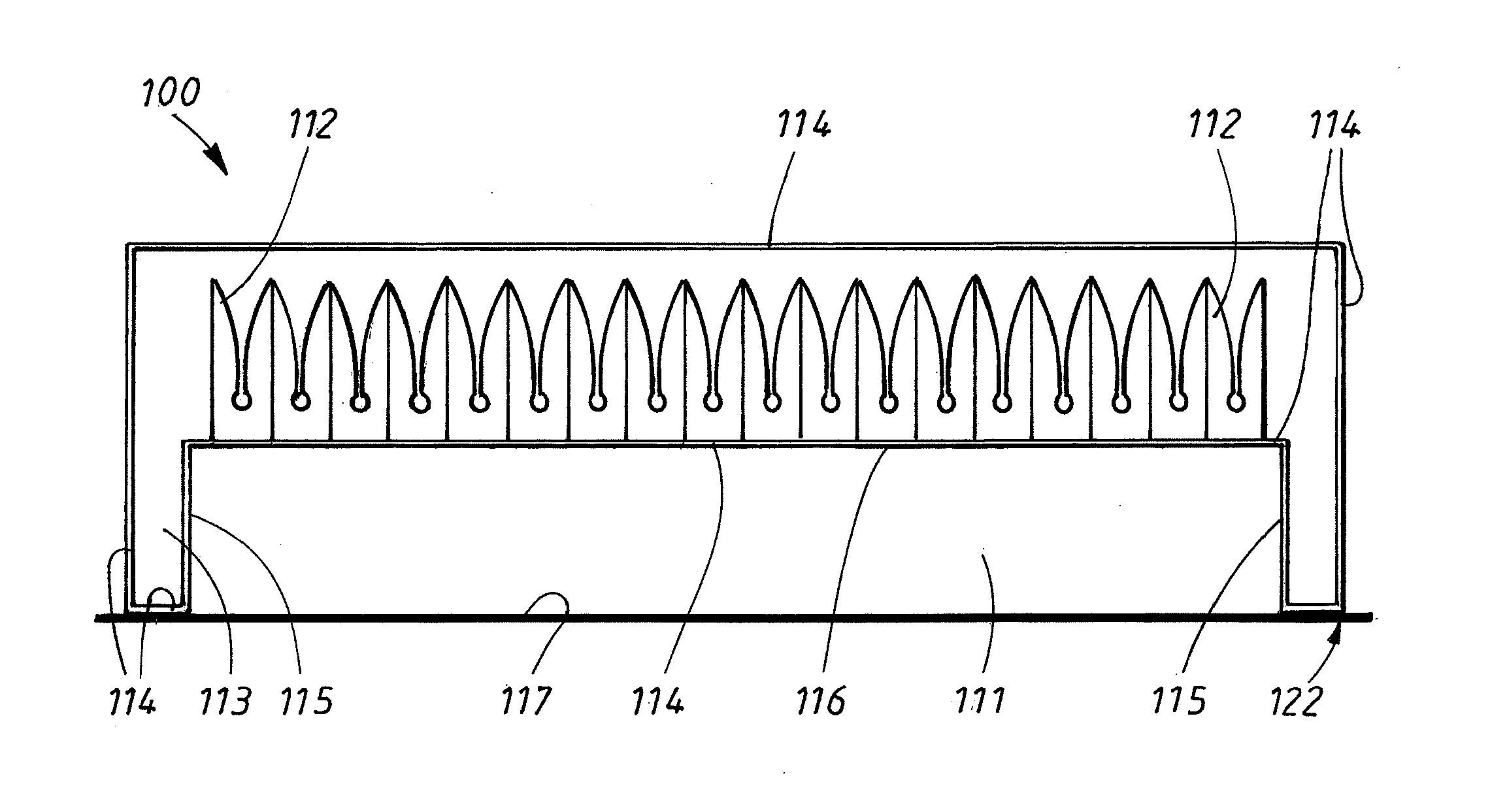
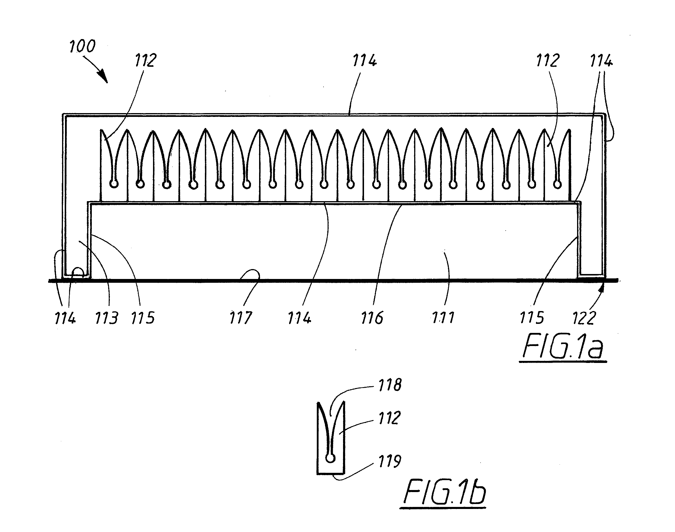
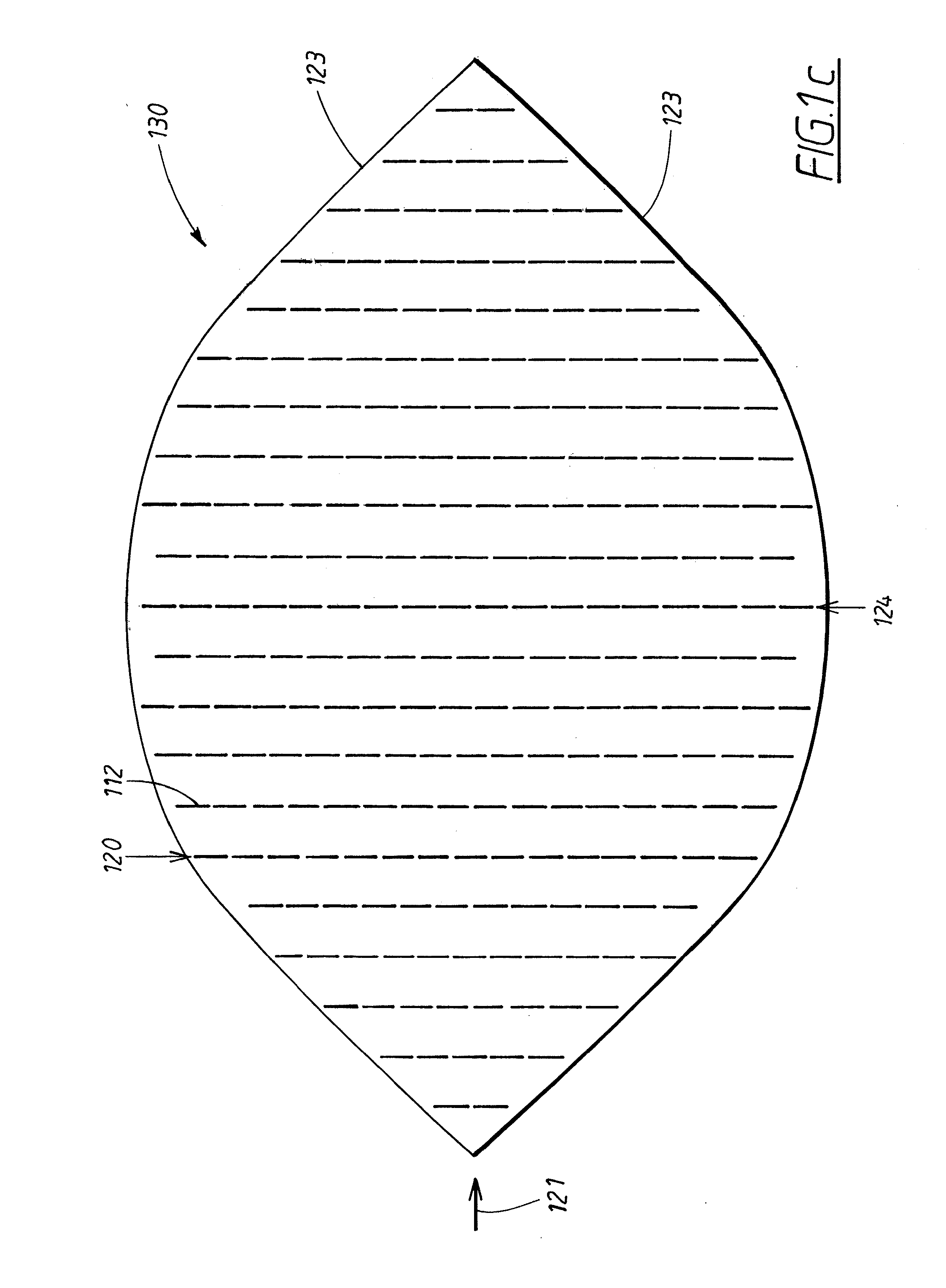
[0037]The invention will now be described in detail with reference to the drawings.

[0038]The stealth AESA is not a very wide-spread concept. There are several design principles such as:[0039]tapered (varying) reflection coefficient over the antenna aperture[0040]absorption of cross-polarized incident waves in the antenna aperture[0041]reduction of scattering from the sides of the AESA[0042]reduction of scattering from the surface on which the AESA is mounted[0043]narrow position tolerances of the antenna elements[0044]equal reflection (in phase and amplitude) in all antenna elements.

[0045]Most of these design principles have been given individual solutions leading to a high degree of complexity, and consequently, a high cost. The invention however provides an overall solution to achieve a low-RCS AESA or a stealth AESA.

[0046]The invention consists of a light but rigid lightweight structure, placed on the AESA. The lightweight material is preferably an electrically isotropic lightwei...


PUM

PropertyMeasurementUnit
slant angleaaaaaaaaaa
dielectricaaaaaaaaaa
magneticaaaaaaaaaa

Abstract

A low-radar cross section antenna structure for an active electrically scanned antenna including an active electrically scanned antenna enclosure and at least two antenna elements. The antenna elements are arranged to be mounted on a front surface of the active electrically scanned antenna enclosure and embedded in a lightweight structure. The front surface and side surfaces of the active electrically scanned antenna enclosure and the antenna elements are arranged to be covered with the lightweight structure. A thin laminate is arranged to cover an outer top surface and an outer side surface of the lightweight structure. Parts of the lightweight structure are arranged to be doped with a lossy material having dielectric, magnetic and / or resistive losses, thus making these parts of the lightweight structure absorbing for electromagnetic radiation.

Description

TECHNICAL FIELD[0001]The present invention relates to the field of low Radar Cross Section (RCS) antennas for objects or vehicles such as fighter aircrafts or missiles. The antennas are of the type Active Electrically Scanned Antenna (AESA).BACKGROUND ART[0002]There is a need today for creating a low radar signature for different objects such as e.g. aircrafts, i.e. to design aircrafts having a low radar visibility. Significant progress has been achieved in a number of problem areas as e.g.:[0003]Intake / exhaust[0004]Cockpit / canopy[0005]Hull or fuselage shape[0006]Absorbers[0007]Armament[0008]but there is often a problem with reducing the passive signature of the aircraft sensors such as antennas.[0009]A number of solutions have been proposed to achieve antennas with a low Radar Cross Section, RCS. The RCS value for an object depends on its size, shape, reflectivity and direction of the signal reflected from the object.[0010]It is now familiar to most that a flat-plate antenna on a m...

Claims


Application Information

Patent Timeline
Patent Type & Authority Applications(United States)
IPC IPC(8): H01Q21/00H01P11/00
CPCH01Q21/061Y10T29/49016H01Q17/00H01Q1/281H01Q21/0087H01Q13/085H01Q1/405H01Q1/40
Inventor HOOK, ANDERS
Owner SAAB AB
Learn More