Multilevel display control list in tile based 3D computer graphics system

Active Publication Date: 2011-12-01
IMAGINATION TECH LTD
View PDF4 Cites 28 Cited by
  • Summary
  • Abstract
  • Description
  • Claims
  • Application Information

AI Technical Summary

Benefits of technology

[0019]Preferred embodiments of the invention provide a method and apparatus for enabling multi level display control lists in a tile based 3D computer graphics system. This reduces the amount

Problems solved by technology

In a tile based rendering system triangles covering multiple tiles consume memory and ba

Method used


Image

  • Multilevel display control list in tile based 3D computer graphics system
  • Multilevel display control list in tile based 3D computer graphics system
  • Multilevel display control list in tile based 3D computer graphics system

Examples


Example

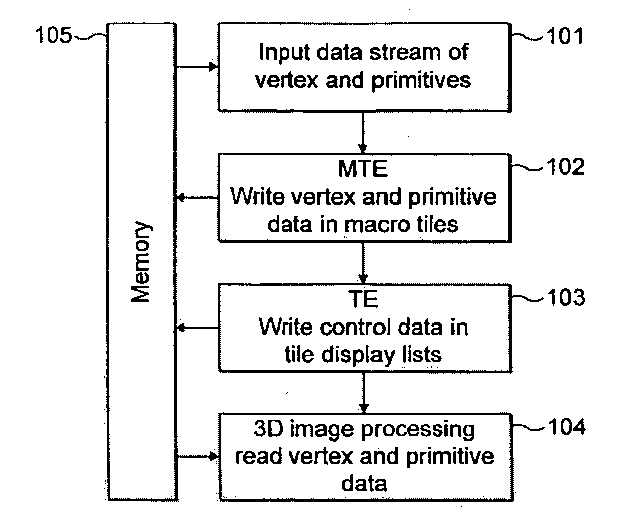
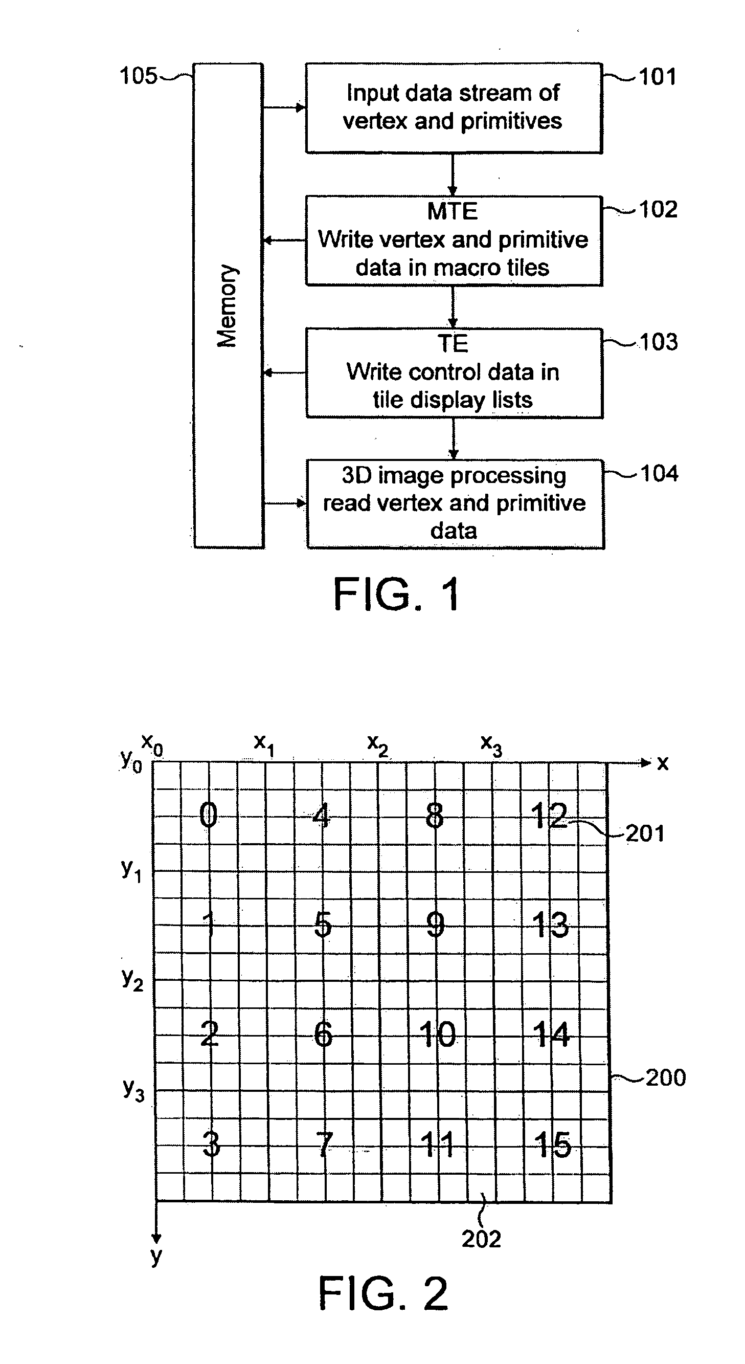
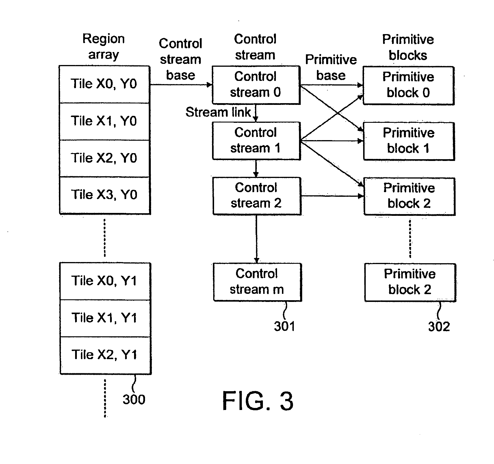
[0034]In a tile based 3D computer graphics system as described above, the Tiling Engine takes primitive blocks from the Macro Tiling Engine and computes the minimum number of tiles needed to render the primitives. The minimal list of tiles is then processed and a primitive block pointer for the address of the primitive block data along with a primitive header word describing the primitives present in the tile are written to dynamically allocated memory as control stream data at 301 in FIG. 3.

[0035]Each tile has its own fixed size memory space used for the control stream data. The memory blocks in this space are allocated on demand by the tile based 3D computer graphics system. When new data to be added to the control stream for a particular tile exceeds the current memory blocks allocated, a new block allocation is requested and the old control stream is linked to the new block allocation using a stream link. If the Macro Tiling Engine indicates the end of a scene via a terminate si...


PUM


Abstract

A method and apparatus are provided for rendering a 3 dimensional computer graphics image. The image is divided into plurality of rectangular tiles which are arranged in a multi level structure comprising a plurality of levels of progressively larger groupings of tiles. Image data is divided into a plurality of primitive blocks and these are assigned to groupings of tiles within the multi level structure in dependence on the groupings each one intersects. Control stream data is derived for rendering the image and this comprises references to primitive blocks for each grouping of tiles within each level of the multi level structure, the references corresponding to the primitive blocks assigned to each grouping and control stream data is used to render the primitive data into tiles within the groupings of tiles for display. This is done such that for primitive blocks which intersect a plurality of tiles within a grouping, control stream data is written for the grouping of tiles rather than for each tile within the grouping.

Description

FIELD OF THE INVENTION[0001]This invention relates to 3-dimensional computer graphics systems, and in particular to systems which use tile based rendering.BACKGROUND TO THE INVENTION[0002]As processing power has increased, the complexity of 3-dimensional computer generated images has also increased. Computer models for very complicated 3D objects, like human movements using vertices and triangle meshes have become easier to generate. This kind of 3D model can be sent to a 3D computer graphics system and animated 3D images generated on a computer screen. Computer generated 3D animated images are widely used in 3D computer games, navigation tools and computer aided engineering design tools.[0003]3D computer graphics systems have to cope with demands for more complex graphics and faster speed display. As the details in the display model increase, more and more primitives and vertices are used. Also, as the texture and shading techniques evolve, more and more information is attached to ...

Claims


Application Information

Patent Timeline
IPC IPC(8): G06T15/00
CPCG06T15/005G06T11/40
Inventor YANG, XILE
Owner IMAGINATION TECH LTD
Why Eureka
Try Eureka