Light reflective structure and light panel

a technology of light reflection and light panel, which is applied in the direction of lighting and heating apparatus, semiconductor devices for light sources, instruments, etc., can solve the problems of high energy consumption, inefficient and fragile, and high heat consumption, and achieve the effect of less light intensity, more coverage, and less coverag

Inactive Publication Date: 2011-12-01
LUXINGTEK
View PDF17 Cites 39 Cited by
  • Summary
  • Abstract
  • Description
  • Claims
  • Application Information

AI Technical Summary

Benefits of technology

[0010]To achieve the abovementioned objective, the present invention discloses a light panel, which comprises a PCB substrate, a top conductor layer, a bottom conductor layer, a plurality of through holes, a control circuit, a plurality of light sources, a light reflective structure, and a diffuser layer. The light reflective structure comprises a plurality of concaves. Each of the concaves has a reflective surface to redirect all of the lights generated from the light sources upwards. The diffuser layer has a plurality of protrusions, and each protrusion has a different thickness profile which reduces the light intensity when the light, provided by the light sources, passes through the thicker region. In addition, the diffuser layer also has a sloping inner surface which reflects and scatters the lights sideways, and the lights generated from the light sources can be much more uniformized.
[0011]The present invention further provides a light panel, which comprises a PCB substrate, a top conductor layer, a bottom conductor layer, a plurality of through holes, a control circuit, a plurality of light sources, a light reflective structure, a diffuser layer, and a plurality of patterned diffuser coatings. The patterned diffuser coatings are coated on the top surface or bottom surface of the diffuser layer. The patterned diffuser coatings are distributed so that the regions that are closer to the light sources have more coverage while the regions that are further from the light sources have less coverage. The stronger lights at the central region are scattered more due to the larger coverage of the patterned diffuser coatings, while the weaker lights provided at the peripheral region will be scattered less due to less coverage of the patterned diffuser coatings. Therefore, the patterned diffuser coatings provide an improvement in uniformizing the overall light output. In this light panel, the diffuser layer may have either a sloping inner surface or a flat inner surface.

Problems solved by technology

Both incandescent and fluorescent light sources have significant disadvantages since they consume a lot of power, produce a great deal of heat, are relatively inefficient and fragile, and have a short lifetime which results in frequent replacements.
Moreover, fluorescent light sources contain mercury which is not environmental friendly and require complicated circuitry and substantial space for the location of the fluorescent lamps and circuitry thus, increasing the profile of the light panel.
So, for a light panel having the diffuser layer disposed too close to the LED light sources, the light output will be non-uniform and hot spots (i.e. the strongest light output intensity area) will be observed.
The hot spots are usually located above the LED light sources, and severely affect the display quality of the light panel.

Method used


Image

  • Light reflective structure and light panel
  • Light reflective structure and light panel
  • Light reflective structure and light panel

Examples


first embodiment

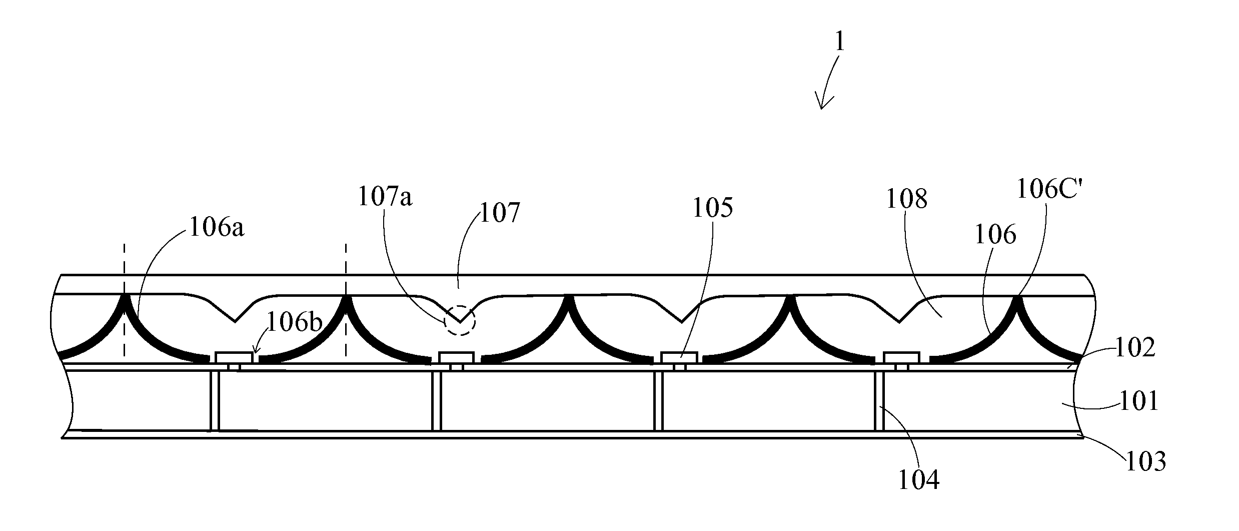
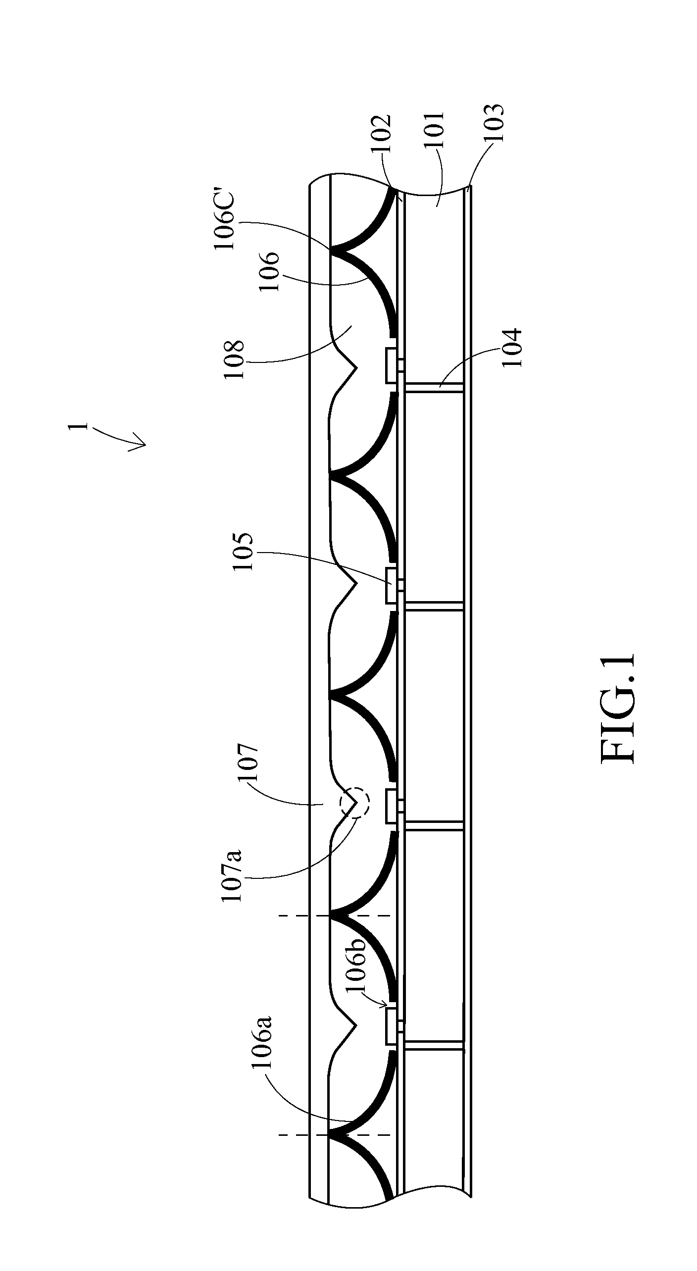
[0039]First, FIG. 1 illustrates a cross sectional view illustrating the light panel 1 in accordance with the present invention. The light panel 1 comprises a circuit assembly, which has a PCB substrate 101, a top conductor layer 102, a bottom conductor layer 103, a plurality of through holes 104, and a control circuit (not shown), and further comprises a plurality of light sources 105, a light reflective structure 106, and a diffuser layer 107.

[0040]In such a circuit assembly of the present embodiment, the top conductor layer 102 is formed on the top surface of the PCB substrate 101 and has a plurality of conductor lines (not shown) for circuit layout. More specifically, the top conductor layer 102 is a patterned electrode layer. The bottom conductor layer 103 is formed on the bottom surface of the PCB substrate 101 (i.e. below the PCB substrate 101) and has a plurality of conductor lines (not shown) for circuit layout. The through holes 104 are formed in the PCB substrate 101 to el...

second embodiment

[0055]The material of the patterned diffuser coatings 908 is polymer resin containing lighting scattering particles such as titanium dioxide particles, calcium carbonate particles, silica oxide particles, metallic particles, air microvoids, or a derivative thereof. The patterned diffuser coatings 908 can be coated by screen printing, inkjet printing, gravure printing, flexo printing, stamping, metal deposition, etc. Moreover, it should be easy for the people skilled in this field to proceed to coat the patterned diffuser coatings on the bottom surface of the diffuser layer in other modifications of the

[0056]To obtain more uniform lights, people skilled in this art may proceed with other modifications according to the recited technical features of the present invention. As shown in FIG. 9B, which illustrates a cross sectional view illustrating the light panel 9′ in accordance with a modification of the second embodiment, the light panel 9′ is similar to the light panel 9 except for t...


PUM


Abstract

A light panel is disclosed. The light panel comprises a circuit assembly, a plurality of light sources, a light reflective structure, and a diffuser layer. The light reflective structure has a plurality of concaves, which are continuously connected to form a plurality of ridges. Each of the concaves has an opening formed on the bottom surface thereof, and each of the light sources is disposed corresponding to each of the openings of the concaves. The diffuser layer is supported by the ridges of the light reflective structure. In some aspects of the present invention, the diffuser layer may have a sloping inner surface or is coated with patterned diffuser coatings on the top surface. Each light source can be added with a lens.

Description

[0001]This application claims priority to U.S. Provisional Application No. 61 / 349,522 filed on May 28, 2010, the disclosures of which are incorporated herein by reference in their entirety.CROSS-REFERENCES TO RELATED APPLICATIONS[0002]Not applicable.BACKGROUND OF THE INVENTION[0003]1. Field of the Invention[0004]The present invention provides a light reflective structure for a light panel, as well as the light panel itself. In particular, the present invention provides a light panel which comprises a light reflective structure for uniformizing the light distribution.[0005]2. Descriptions of the Related Art[0006]Conventional light panels typically employ incandescent or fluorescent light sources. Both incandescent and fluorescent light sources have significant disadvantages since they consume a lot of power, produce a great deal of heat, are relatively inefficient and fragile, and have a short lifetime which results in frequent replacements. Moreover, fluorescent light sources contai...

Claims


Application Information

Patent Timeline
Patent Type & Authority Applications(United States)
IPC IPC(8): F21V7/00F21V5/00
CPCF21V3/02F21V5/007F21Y2101/02F21Y2105/001G09F13/14F21V7/0083F21Y2105/16F21Y2115/10
Inventor ING, WEN-CHIUNHOU, WEI-HSINKOH, ZHI-WEIKAO, CHI-JEN
Owner LUXINGTEK
Why Eureka
Try Eureka