Near-field light emitting device, optical recording head and optical recorder

Inactive Publication Date: 2011-12-01
KONICA MINOLTA OPTO
View PDF12 Cites 18 Cited by
  • Summary
  • Abstract
  • Description
  • Claims
  • Application Information

AI Technical Summary

Benefits of technology

[0021]According to the present invention, it is possible to provide a near-field light emitting device that emits near-light efficiently b

Problems solved by technology

In a magnetic recording system, an increase in the recording density causes the magnetic bit to be subjected to a serious impact from the outdoor temperature and other

Method used


Image

  • Near-field light emitting device, optical recording head and optical recorder
  • Near-field light emitting device, optical recording head and optical recorder
  • Near-field light emitting device, optical recording head and optical recorder

Examples


Embodiment Construction

[0045]The following describes the present invention with reference to an optically assisted magnetic recording head wherein the optical recording head as an embodiment of the present invention is equipped with a magnetic recording section, and an optical recorder provided with the aforementioned optically assisted magnetic recording head, without the present invention restricted thereto. For example, the optical recording head as an embodiment of the present invention is also applicable to recording on an optical magnetic medium instead of an optical magnetic recording medium. In the following description, like parts or corresponding parts in various forms of embodiments are designated by the like reference numbers, and a duplicated explanation will be omitted, as appropriate.

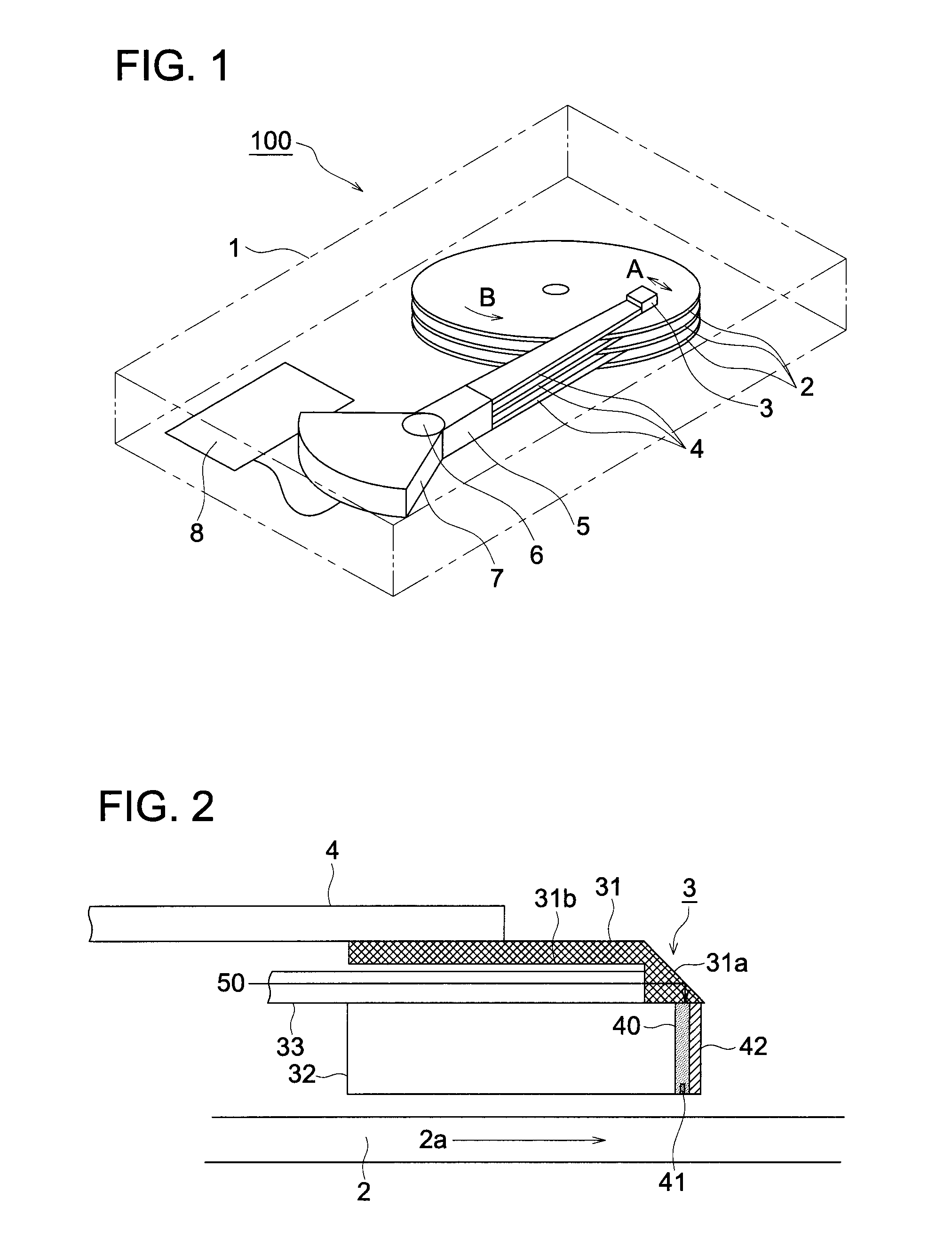
[0046]FIG. 1 shows the approximate structure of an optical recorder (e.g., hard disk apparatus) provided with an optically assisted magnetic recording head in the present embodiment. This optical recorder 100 h...


PUM


Abstract

Provided is a near-field light emitting device which emits near-field light efficiently by simple structure. A near-field light emitting device comprises a waveguide which is equipped with a core and a clad touching the core and is coupled with light having an electric field component in the direction perpendicular to the boundary surface of the core and clad, and a planar metal structure which is arranged along the above-mentioned boundary surface where the electric field component is in the perpendicular direction. The metal structure has a tip adjoining the light exit surface of the core, and a side projecting to the clad where the width of the metal structure in the direction perpendicular to the propagation direction of the light coupled with the waveguide is wider than the width of the core.

Description

FIELD OF THE INVENTION[0001]The present invention relates to a near-field light emitting device, optical recording head and optical recorder.DESCRIPTION OF RELATED ART[0002]In a magnetic recording system, an increase in the recording density causes the magnetic bit to be subjected to a serious impact from the outdoor temperature and other factors. This requires a recording medium having a high level of coercive force. Use of such a recording medium increases the magnetic field required for recording. The upper limit of the magnetic field produced by the recording head is determined by the saturation magnetic flux density. The value thereof has come close to the limit of the material. Accordingly, a drastic increase cannot be hoped for.[0003]To solve this problem, the following proposal has been made, for example. Magnetic softening is produced by local heating. When the magnetic coercive force has been reduced, recording is started. After that, heating is suspended, and the material...

Claims


Application Information

Patent Timeline
IPC IPC(8): G11B13/08G02B6/26G11B7/12G11B7/135
CPCG02B6/122G02B6/1228G11B5/314G11B5/6088G11B2005/0021G11B7/1384G11B7/1387G11B2005/0005G11B7/122
Inventor OSAWA, KOUSEKINE, KOUJIROU
Owner KONICA MINOLTA OPTO
Why Eureka
Try Eureka