
Enhanced intra prediction mode signaling

a prediction mode and signaling technology, applied in signal generators with optical-mechanical scanning, color televisions with bandwidth reduction, etc., can solve the problems of less efficient data compression and soon become a burden, and achieve the effect of reducing the maximum length of binary codewords, and high probability

Active Publication Date: 2011-12-01
LG ELECTRONICS INC
View PDF6 Cites 192 Cited by
  • Summary
  • Abstract
  • Description
  • Claims
  • Application Information

AI Technical Summary

Benefits of technology

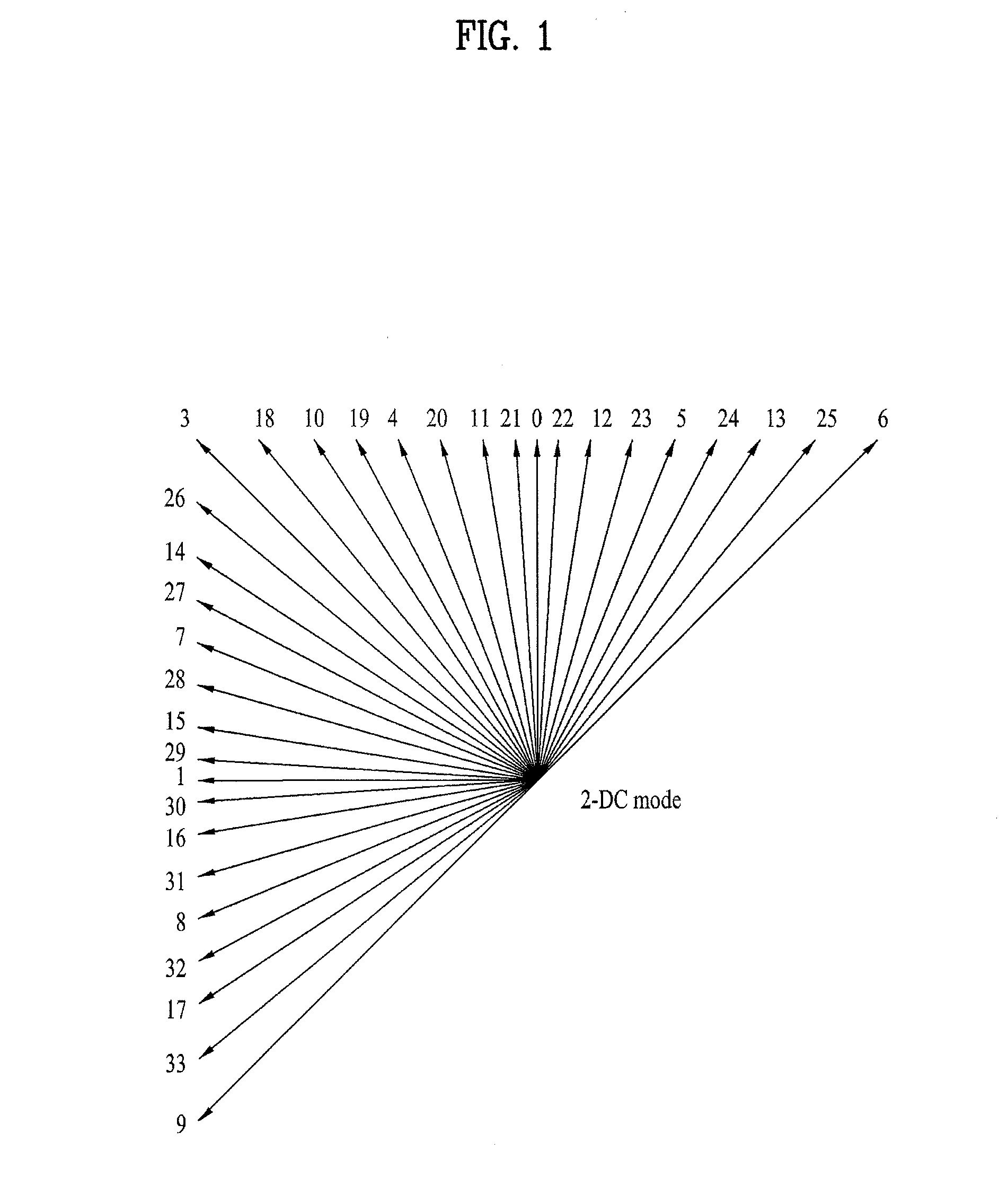
[0012]To achieve this objective and other advantages according to the present invention, as embodied and broadly described herein, an aspect of the present invention is to identify an intra prediction mode for a current prediction block by referencing the intra prediction modes used to predict blocks of video data that neighbor a current prediction block. So while unique codewords, or index values / numbers, may be required to identify the intra prediction modes processed to predict the neighboring blocks of video data, the intra prediction mode that corresponds to predicting the current prediction may be identified by simply referring to one these previously identified intra prediction modes. Because there is a high probability that a current prediction block will be predicted according to a same intra prediction mode used to predict a block of video data that neighbors the current prediction block, simply referencing to the previously identified intra prediction mode offers a method for reducing the maximum length of a binary codeword required to identify the proper intra prediction mode for predicting the current prediction block.
[0013]Another object of the present invention is to identify an intra prediction mode for a current prediction block by grouping a number of available intra prediction modes into distinct groups. Then instead of uniquely identifying all of the available intra prediction modes, an intra prediction mode for predicting a current prediction block may be identified by referring to a particular group of intra prediction modes and an index within the particular group. Because the number of groups that will be used to group the available intra prediction modes will be less than the total number of available intra prediction modes, this offers a method for reducing the maximum length of a binary codeword required to identify the proper intra prediction mode for predicting the current prediction block.
[0014]Another object of the present invention is to identify an intra prediction mode for predicting a current prediction block by identifying the intra prediction mode as an offset of a previously identified intra directional prediction mode. So by simply identifying an offset value in relation to a previously identified intra directional prediction mode, the present invention offers a method for reducing the maximum length of a binary codeword required to properly identify the intra prediction mode for predicting a current prediction block.

Problems solved by technology

However, as the number of intra prediction modes made available increased, it soon became a burden to assign each intra prediction mode its own unique codeword from a data size standpoint.
Not only was the encoding unit burdened with encoding the identifying information to account for all of the available intra prediction mode codewords, the decoding unit too was burdened with accounting for all of the available intra prediction mode codewords.
The more binary bits that are needed to create a unique codewords directly corresponds to the data size of the encoded video signal, and this in turn leads to less efficient compression of data.

Method used


Image

  • Enhanced intra prediction mode signaling
  • Enhanced intra prediction mode signaling
  • Enhanced intra prediction mode signaling

Examples


second embodiment

[0063]Now according to a first example of the second embodiment, FIG. 6 illustrates that the MPM has been determined to be intra prediction mode a. Then the index values corresponding to the intra prediction modes of the remaining available neighboring blocks are seen to share the following initial index number relationship:

intra prediction mode e

[0064]Then according to case 1, all of the remaining known intra prediction modes as depicted in the Initial Mode Index of FIG. 5 will be shifted after taking out intra prediction mode a that was determined to be the MPM. So in FIG. 6, case 1 illustrates that after taking out intra prediction mode a that was determined to be the MPM, all the remaining known intra prediction modes are shifted up such that the intra prediction mode having the next lowest initial index value after the MPM intra prediction mode will be assigned the lowest index value value ‘0’. Thus intra prediction mode b is shif...

third embodiment

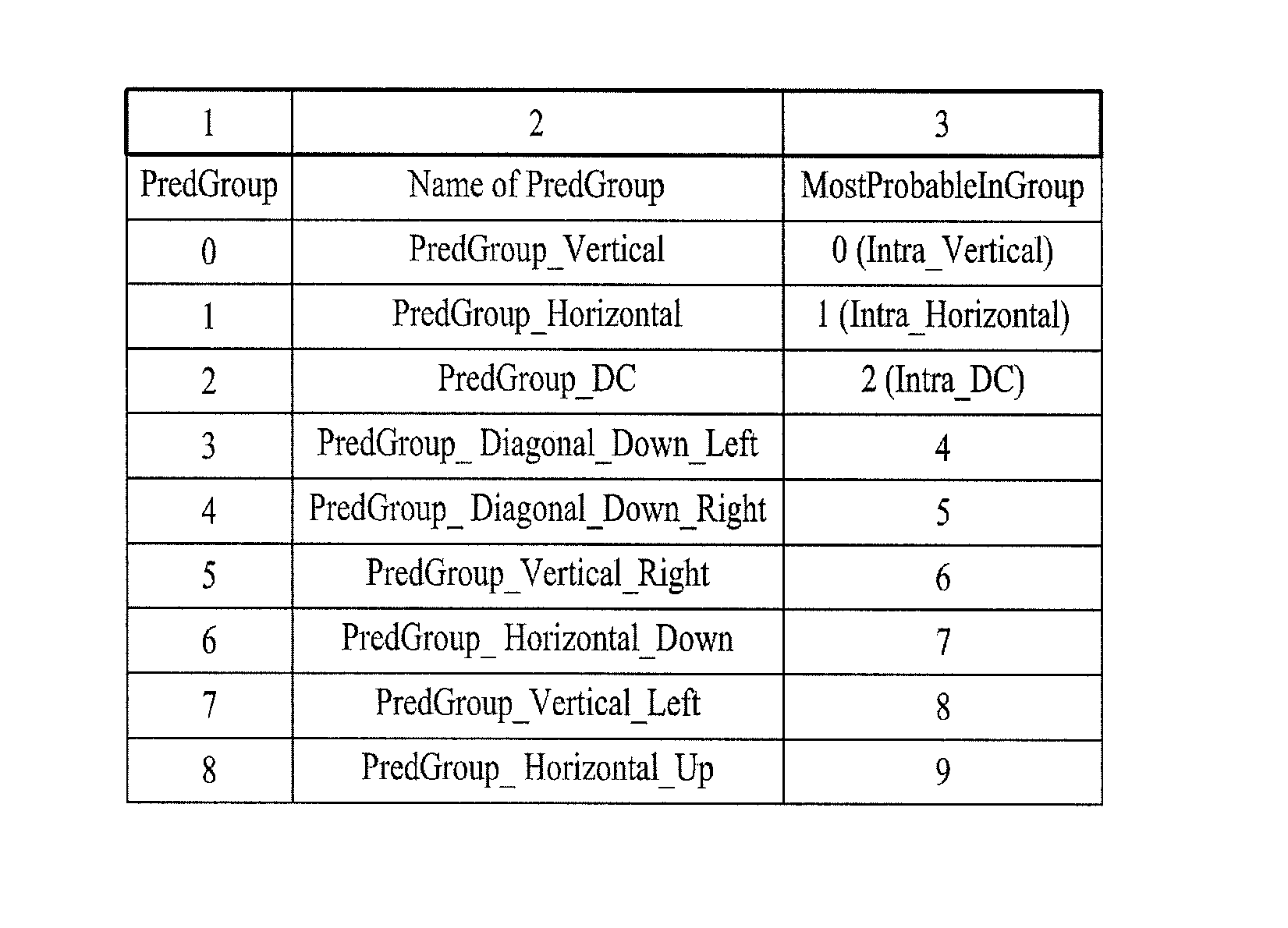
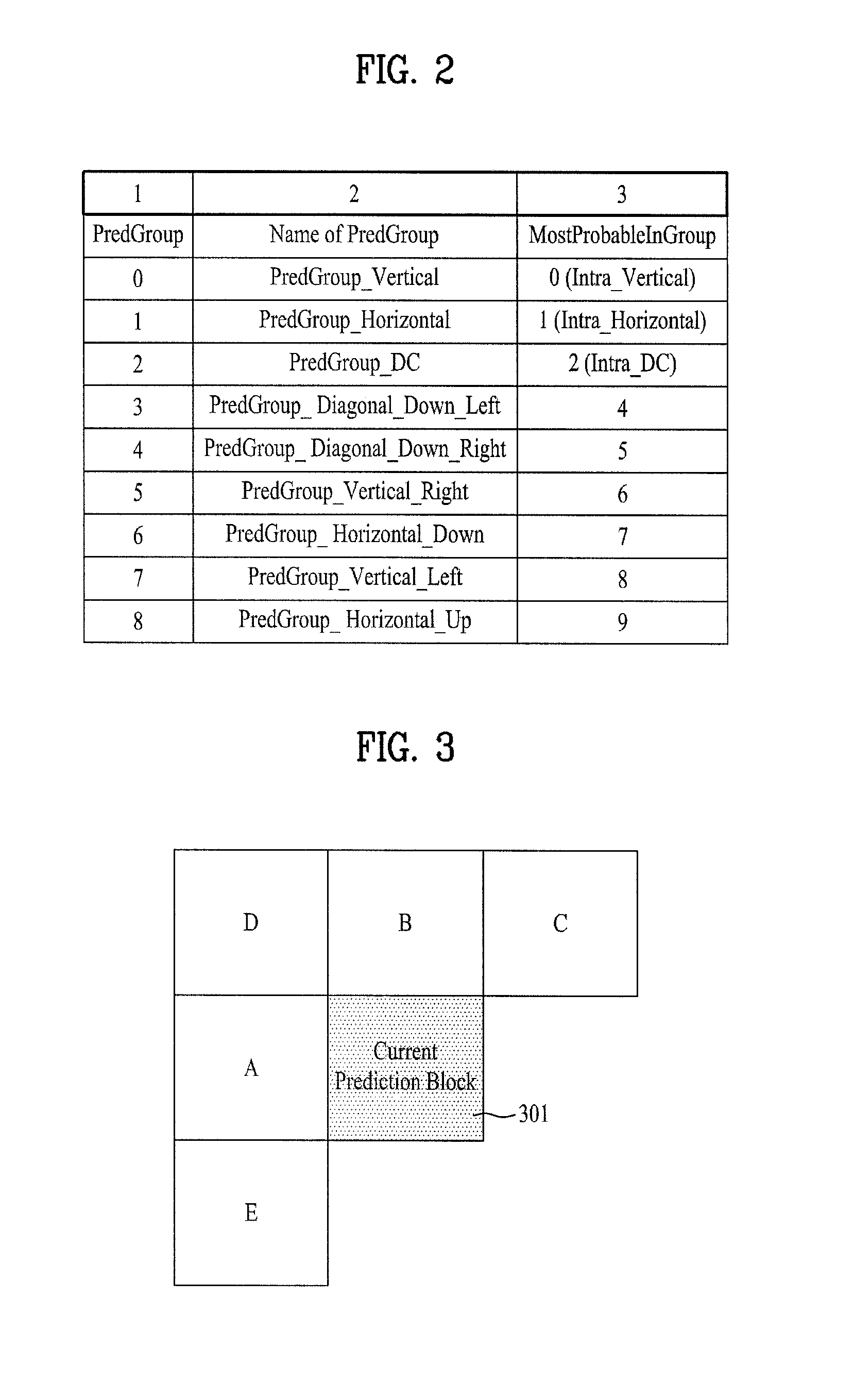
[0096]Intra prediction modes may be assigned to a particular prediction group randomly. Or preferably, similar intra prediction modes will be assigned to a common prediction group. FIG. 2 provides one example of assigning intra prediction modes into particular prediction groups. Columns one and two of the table illustrated in FIG. 2 identify the prediction group number and name for each prediction group, respectively, and column 3 identifies the intra prediction mode that is designated to be the MPM from among the intra prediction modes included in the corresponding prediction group. And according to an aspect of the third embodiment, the MPM intra prediction mode identified in column 3 will also be assigned the lowest index value within its own prediction group.

[0097]A fourth embodiment of the present invention looks to offer a method for reordering the index order for intra prediction modes when the MPM from the prediction group is not selected. This fourth embodiment looks to reo...

fourth embodiment

[0098]According to a first option of the fourth embodiment, for each instance of predicting a current prediction block, one of the intra prediction modes from a prediction group including the MPM intra prediction mode for the current prediction block will be assigned the lowest index position within the prediction block. Specifically, this first option calls for assigning the intra prediction mode having the lowest initial identifying index value to the lowest index position within the prediction group. All remaining intra prediction modes will have their position within the prediction group shifted, while maintaining their original position order within the prediction group, following the intra prediction mode assigned to the new lowest prediction group index position.

[0099]According to a second option of the fourth embodiment, for each instance of predicting a current prediction block, one of the intra prediction modes from a prediction group including the MPM intra prediction mod...


PUM


Abstract

A method and apparatus for signaling and receiving a video signal for processing is disclosed. Methods for determining a most probable mode for predicting a current prediction block are provided as well as new methods for grouping intra prediction modes into prediction groups. Methods for predicting a prediction block of video data as well as signaling intra prediction modes are also provided.

Description

[0001]Pursuant to 35 U.S.C. §119(e), this application claims the benefit of U.S. Provisional Application No. 61 / 349,887 filed on May 30, 2010, U.S. Provisional Application No. 61 / 351,266 filed on Jun. 3, 2010, U.S. Provisional Application No. 61 / 375,287 filed on Aug. 20, 2010, U.S. Provisional Application No. 61 / 409,978 filed on Nov. 4, 2010, and U.S. Provisional Application No. 61 / 410,369 filed on Nov. 5, 2010, all of which are hereby incorporated by reference as if fully set forth herein.BACKGROUND[0002]1. Field of the Invention[0003]The present invention relates to a method and apparatus for signaling the proper intra prediction mode to be processed for each corresponding prediction block of video data included in a digital video data transmission.[0004]2. Discussion of the Related Art[0005]A digital video signal is comprised of a sequence of digital video frames that are a representation of an original RGB video signal. As part of the analog-to-digital signal transformation, eac...

Claims


Application Information

Patent Timeline
IPC IPC(8): H04N7/32H04N7/26H04N19/593
CPCH04N19/182H04N19/154H04N19/513H04N19/59H04N19/159H04N19/18H04N19/105H04N19/176H04N19/46H04N19/196H04N19/61H04N19/593H04N19/11H04N19/463H04N19/14H04N19/50H04N19/70
Inventor LIM, JAEHYUNKIM, JUNGSUNPARK, SEUNGWOOKSUNG, JAEWONJEON, BYEONGMOONPARK, JOONYOUNGJEON, YONGJOONCHOI, YOUNGHEE
Owner LG ELECTRONICS INC
Learn More