

Central venous access system
a central venous access and catheter technology, applied in the direction of trocar, catheter, infusion syringe, etc., can solve the problems of venous occlusion, short-term and long-term complications, and uncertainty about the location, depth and entry angle of the puncture needle, so as to achieve the effect of avoiding venous occlusion and long-term risks of central access
- Summary
- Abstract
- Description
- Claims
- Application Information
AI Technical Summary
Benefits of technology
Problems solved by technology
Method used
Image

Examples
Embodiment Construction
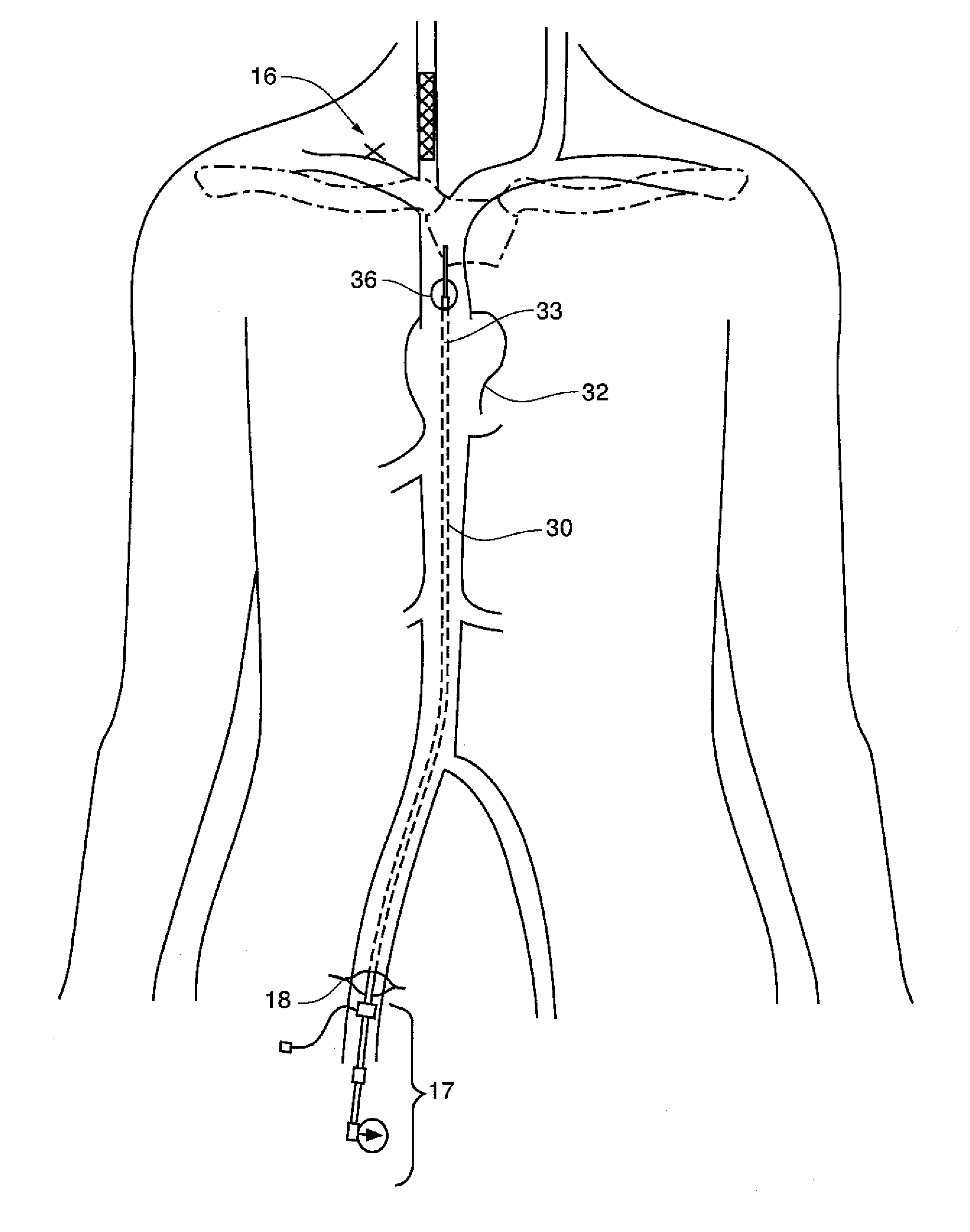
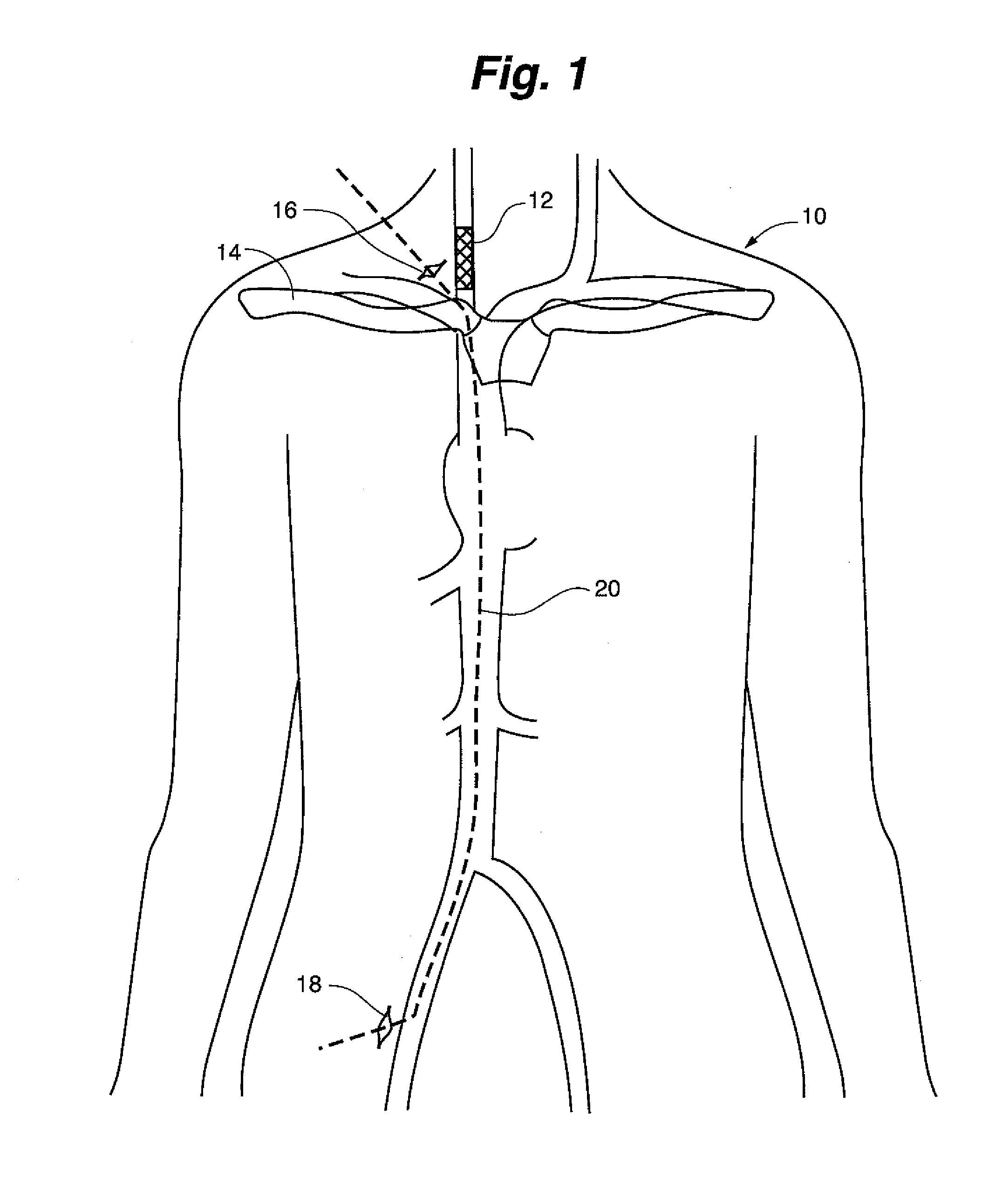
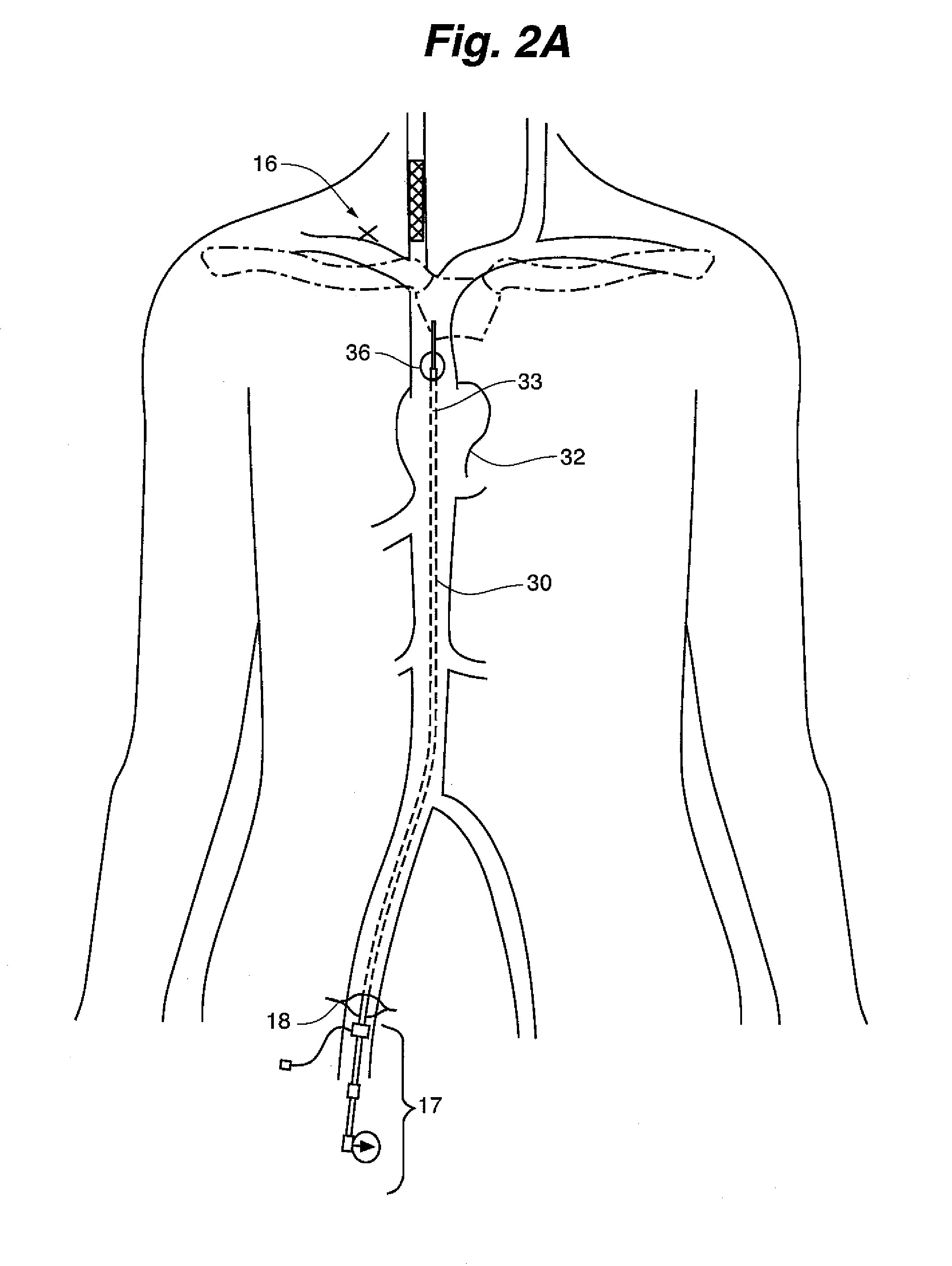
[0025]One of the most clinically significant uses of the devices and methods of this invention pertains to right-sided supraclavicular access because it combines the preferred location for long-term catheters, the most common site of chronic venous occlusions, and the most straightforward application of the invention. Therefore this procedure has been selected as an illustrative but not limiting example of the techniques and suitable hardware implementations of the catheter system invention. The invention is illustrated in the context of a patient having an occluded right internal jugular vein which is recovered by use of the method and catheter system to place a new access point near the one lost to the occlusion. In contrast to the conventional practice that would sacrifice companion vessels, the illustration achieves re-entry very near a lost CVA location.
[0026]FIG. 1 shows the context of the invention and presents the interventional path with respect to certain anatomic referenc...
PUM
 Abstract
Description
Claims
Application Information