Reinforced hose assembly

a hose and hose body technology, applied in the direction of pipes, mechanical equipment, other domestic objects, etc., can solve the problems of increasing the cost of pumping and fluid transfer, affecting the cleaning effect of the system, and affecting the application of the system, so as to achieve the effect of forming small bend radii, adequate structural rigidity and strength, and less turbulen

Active Publication Date: 2011-12-08
KONGSBERG ACTUATION SYST II
View PDF8 Cites 7 Cited by
  • Summary
  • Abstract
  • Description
  • Claims
  • Application Information

AI Technical Summary

Benefits of technology

[0007]The reinforced hose assembly of the present invention possesses adequate structural rigidity and strength and is also capable of forming small bend radii. The uniform inner radial surface is free from corrugation and undulations which results in less turbulence during fluid transport operations. The reinforced hose assembly is also safe for food and medical applications because there is minimal residual content build-up due to the uniform inner radial surface providing ease of cleaning or flushing between materials and batches.

Problems solved by technology

These conventional reinforced hose assemblies may be suitable for most applications where rigidity and strength are of primary importance, but many fail for high pressure applications where a small bend radius is necessary.
These undulations cause pressure drops and flow disturbances throughout the length of the conventional reinforced hose assembly, which adds unnecessary pumping and fluid transfer costs to the application.
These undulations also hold residual material making it difficult to clean the system for applications which use short shelf life materials or applications which use different materials and batches.
The residual material build-up may result in contamination of subsequent material runs.

Method used


Image

  • Reinforced hose assembly
  • Reinforced hose assembly
  • Reinforced hose assembly

Examples


Embodiment Construction

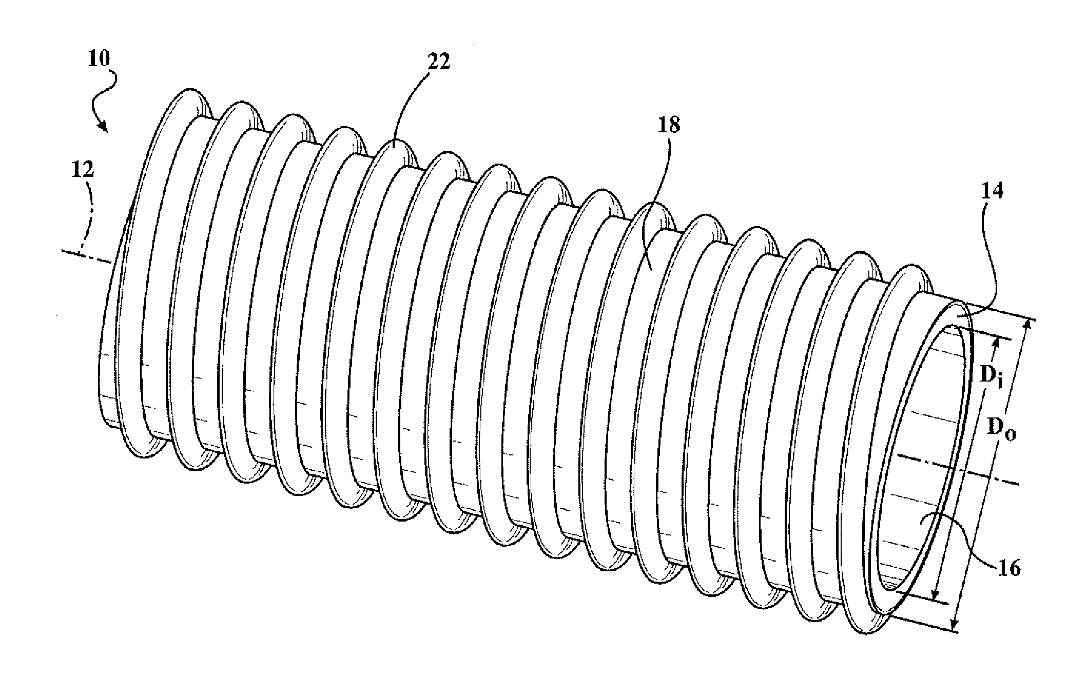
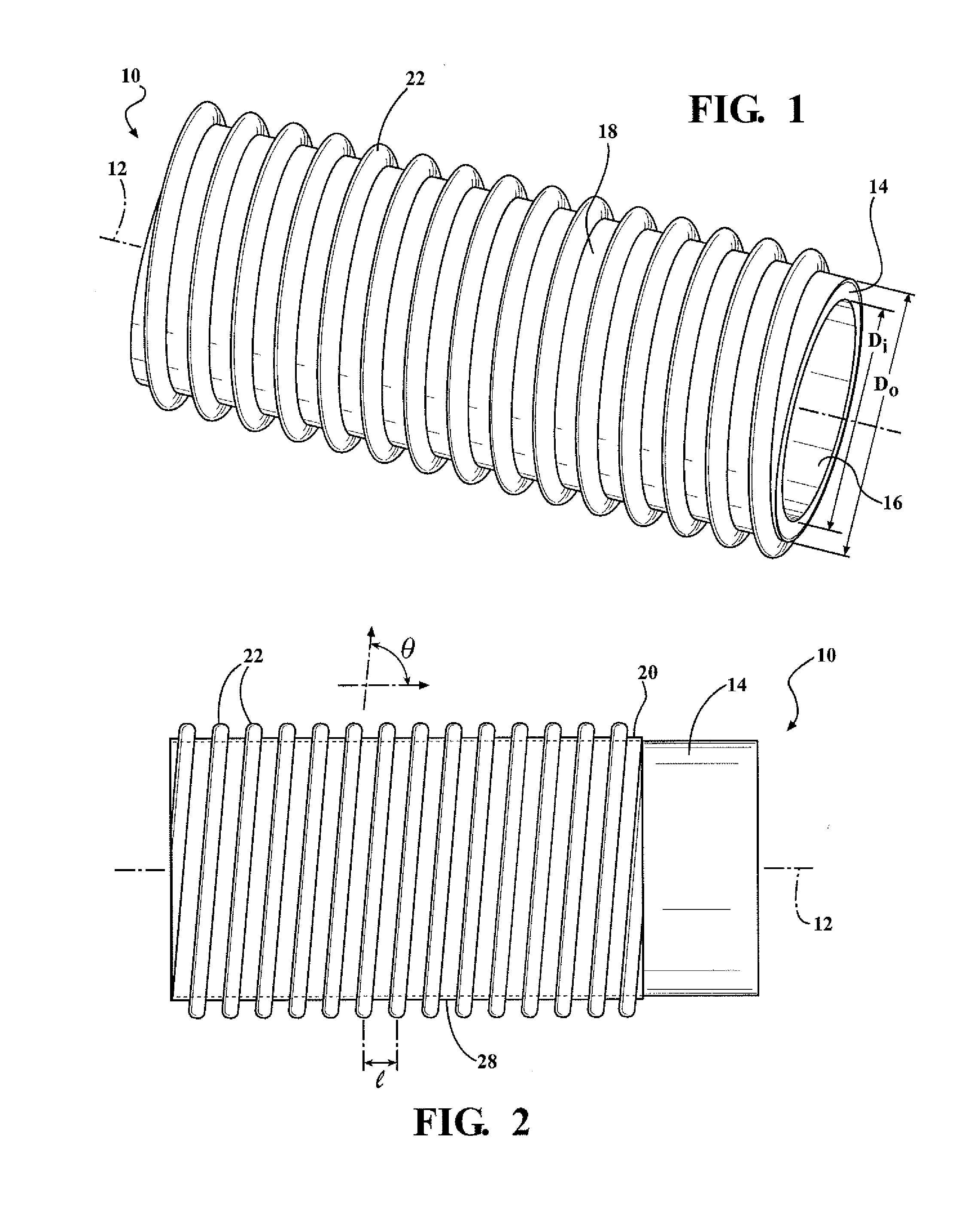
[0016]Referring to FIG. 1, a reinforced hose assembly 10 is provided. In basic dimensions, the reinforced hose assembly 10 may define a longitudinal axis along a length of the reinforced hose assembly 10 such that the reinforced hose assembly 10 may extend axially to any length along the longitudinal axis 12.

[0017]The reinforced hose assembly 10 includes a tubular inner layer 14 having a uniform interior radial surface 16 and an exterior radial surface 18. The tubular inner layer 14 has an inner and outer diameter referenced, respectively, at “Di” and “Do”. The inner and outer diameter dimensions may vary depending on the particular application, but generally will range from 0.1 to 6 inches for inner diameter Di and 0.1 to 6 inches for outer diameter Do, with an overall wall thickness, ranging from 0.01 to 0.5 inches. Alternatively, the inner diameter may range from 0.25 to 3 inches, the outer diameter may range from 0.25 to 3 inches, and the wall thickness may range from 0.05 to 0....


PUM

PropertyMeasurementUnit
thicknessaaaaaaaaaa
outer diameteraaaaaaaaaa
thicknessaaaaaaaaaa

Abstract

A reinforced hose assembly includes tubular inner layers with a uniform interior radial surface and an exterior radial surface. The tubular inner layer defines a longitudinal axis along a length thereof and comprises a first fluorocarbon polymer. The reinforced hose assembly also includes a bonding layer comprising a second fluorocarbon polymer. The bonding layer is disposed about the exterior radial surface of the tubular inner layer. The reinforced hose assembly also includes a reinforcing element comprising the second fluorocarbon polymer, attached to bonding layer and helically disposed about the tubular inner layer at a predetermined helical pitch measured relative to the longitudinal axis of the tubular inner layer.

Description

CROSS REFERENCE TO RELATED APPLICATIONS[0001]This application claims priority to and incorporates by reference U.S. Provisional Patent Application No. 61 / 352,273, which was filed on Jun. 7, 2010.FIELD OF INVENTION[0002]The present invention generally relates to a reinforced hose assembly. The present invention more particularly relates to a reinforced hose assembly that includes a uniform inner radial surface and a reinforcing element.BACKGROUND OF THE INVENTION[0003]Conventional reinforced hose assemblies have been used for the transfer of various fluids, such as gasoline, petroleum-based products, chemicals, food products, and others.[0004]These conventional reinforced hose assemblies may be suitable for most applications where rigidity and strength are of primary importance, but many fail for high pressure applications where a small bend radius is necessary. Furthermore, conventional reinforced hoses have either a smooth inner surface, to allow for turbulence free fluid flow and ...

Claims


Application Information

Patent Timeline
Patent Type & Authority Applications(United States)
IPC IPC(8): F16L11/00B29C48/09B29C48/10B29C48/12B29C48/13B29C48/21
CPCB29C53/58B29C59/103B29C59/142B29K2027/12F16L11/115B29D23/18B29K2027/00B29C47/003B29C47/0033B29C47/065B29K2023/18B29C47/8895B29C47/0023B29C48/10B29C48/913B29C48/09B29C48/12B29C48/13B29C48/919B29C48/21
Inventor HAHN, RICHALIHODZIC, ELVISFETZER, GEORGE
Owner KONGSBERG ACTUATION SYST II
Why Eureka
Try Eureka