
Tire and tire manufacturing method

a technology for tires and manufacturing methods, applied in the direction of transportation and packaging, other domestic articles, and multiple inflatable chambers, can solve the problem of limit to the application of post-use rubber recycling, and achieve the effect of sufficient strength and efficient manufacturing

Active Publication Date: 2011-12-08
BRIDGESTONE CORP
View PDF5 Cites 6 Cited by
  • Summary
  • Abstract
  • Description
  • Claims
  • Application Information

AI Technical Summary

Benefits of technology

[0040]Configuring the tire of the present invention as explained above results in the excellent effect of enabling sufficient strength to be secured at the joint portion. Furthermore, according to the tire manufacturing method of the present invention a tire with sufficient strength secured at the joint portion can be efficiently manufactured.

Problems solved by technology

However, there is a limit to application of post-use recycling of rubber, and disposal is performed by such processes as combustion and shredding for use as pavement materials for roads.

Method used


Image

  • Tire and tire manufacturing method
  • Tire and tire manufacturing method
  • Tire and tire manufacturing method

Examples


first exemplary embodiment

[0069

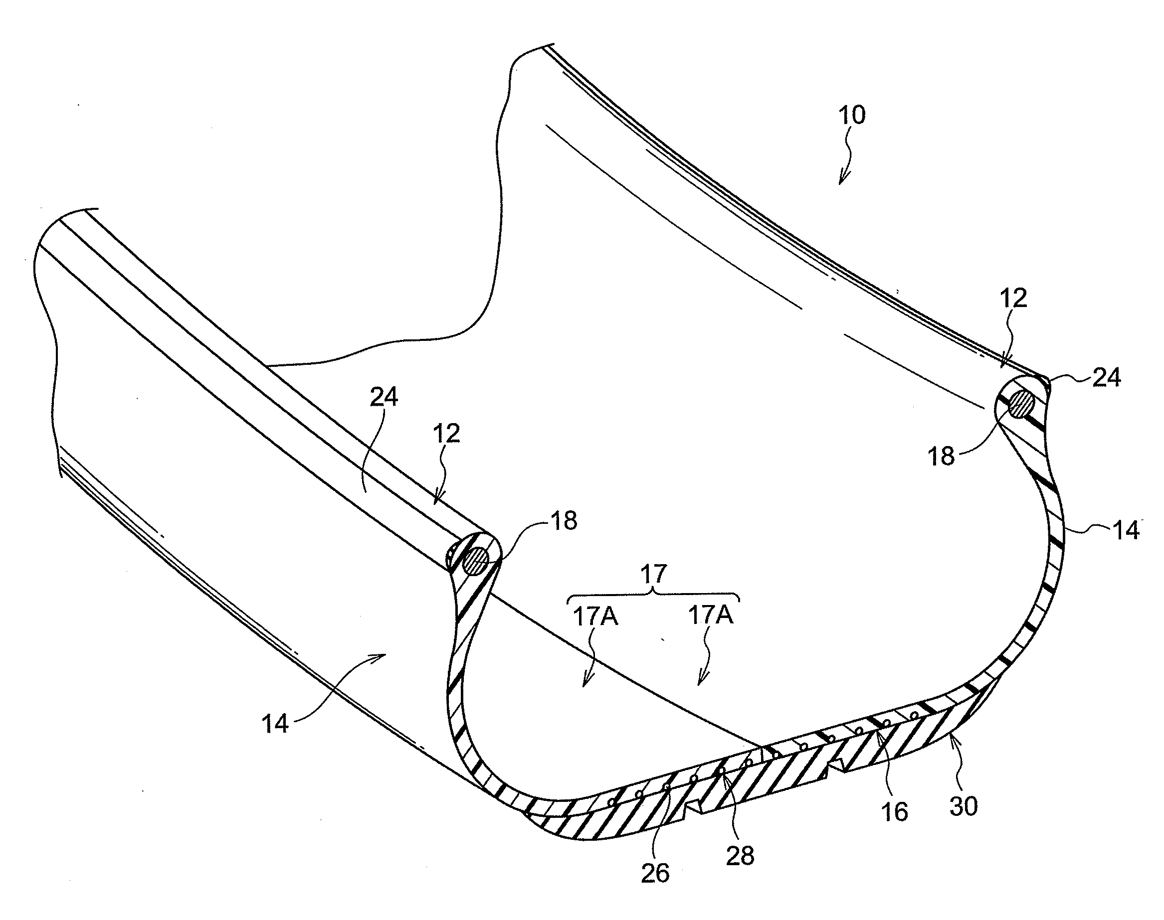
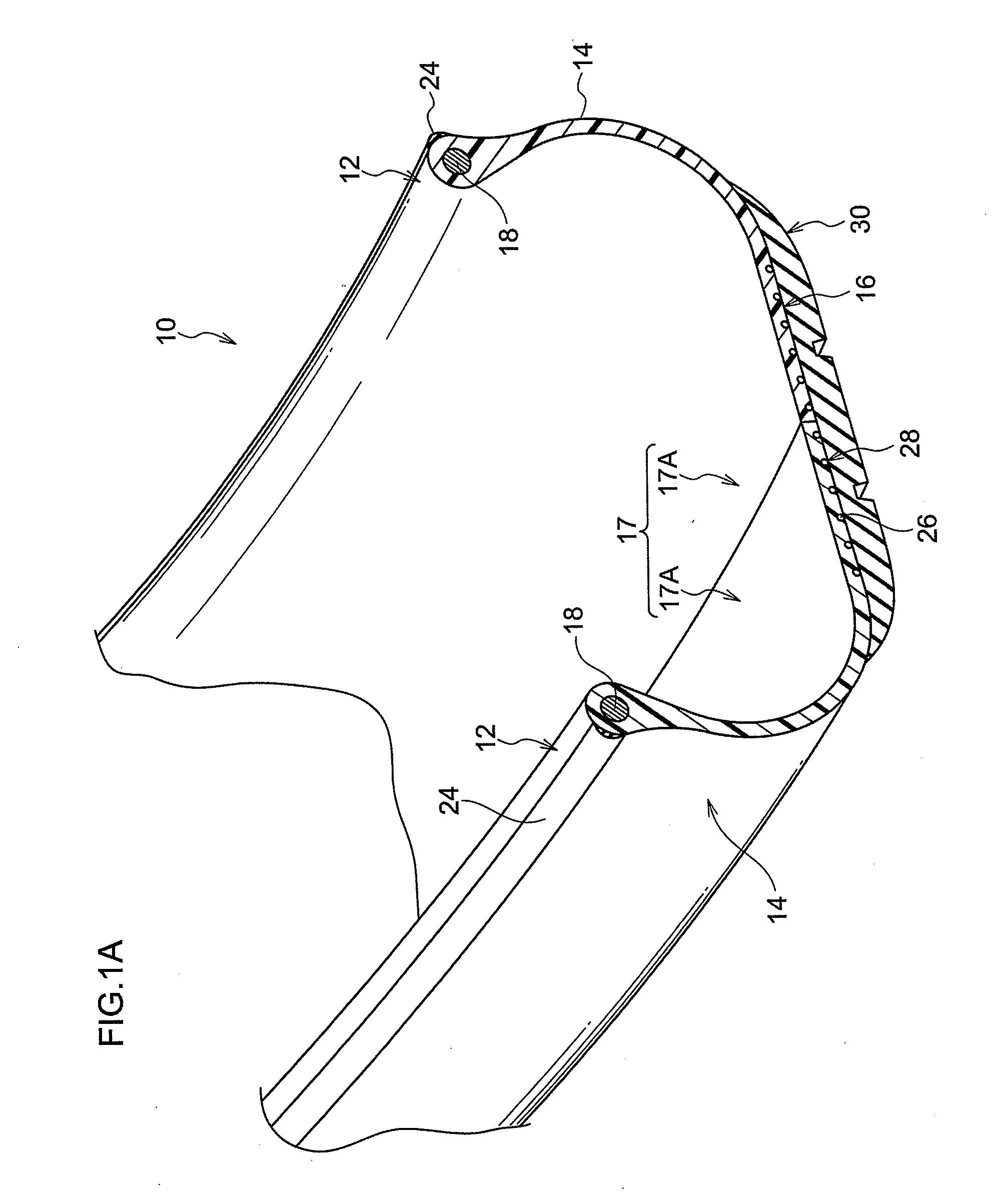
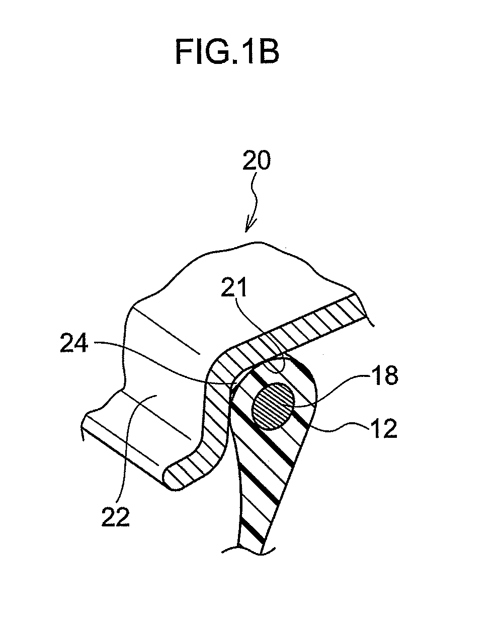
[0070]Explanation follows regarding a tire according to a first exemplary embodiment of the tire of the present invention, with reference to the drawings. As shown in FIGS. 1, a tire 10 of the present exemplary embodiment displays a substantially similar cross-section profile to that of an ordinary conventional rubber pneumatic tire.

[0071]The tire 10 is equipped with a tire case 17 configured from: a pair of bead sections 12 that make contact with a bead seat section 21 and a rim flange 22 of a rim 20; side sections 14 that extend from the bead sections 12 towards the tire radial direction outside; and a crown section 16 that connects together the tire radial direction outside edge of one of the side sections 14 and the tire radial direction outside edge of the other of the side sections 14. The tire case 17 of the present exemplary embodiment is formed from a first thermoplastic material.

[0072]The tire case 17 of the present exemplary embodiment is formed by mutually aligning ...

second exemplary embodiment

[0108

[0109]In the above exemplary embodiment the welding thermoplastic material 43 is supplied to the joint portion in a completely molten state, and one of the tire halves 17A and the other of the tire halves 17A are welded together. However in the second exemplary embodiment a strip shaped welding sheet 74 formed from a thermoplastic material (the second thermoplastic material of the present invention) is welded to both the one of the tire halves 17A and the other of the tire halves 17A, namely welded so as to straddle across the outer peripheral portion of the joining faces of the one of the tire halves 17A and the other of the tire halves 17A, thereby joining together the one of the tire halves 17A and the other of the tire halves 17A. The width of the welding sheet 74 is preferably 5 mm or greater.

[0110]In the joining method of the present exemplary embodiment, as shown in FIG. 13, hot air generated by a heating device 76 configured with a heater and fan is directed against the...


PUM

PropertyMeasurementUnit
widthaaaaaaaaaa
thicknessaaaaaaaaaa
temperatureaaaaaaaaaa

Abstract

A tire configured from joining together plural tire frame members formed from a thermoplastic material in which sufficient strength of the joint portion is secured. Two tire halves 17A formed from a first thermoplastic material are supported by a tire supporting section 40 so as to be aligned with each other and abutting, while rotating this configuration melted welding thermoplastic material 43 is extruded from a nozzle 46 towards the joining location, and the welding thermoplastic material 43 is pressed by a flattening roller 48. The one tire half 17A and the other tire half 17A are thereby welded together with the welding thermoplastic material 43. Since the tire halves 17A themselves are not melted, deterioration of the thermoplastic material forming the tire halves 17A is suppressed, and sufficient strength of the joint portion is secured.

Description

TECHNICAL FIELD[0001]The present invention relates to a tire for rim mounting and tire manufacturing method, and in particular to a tire and tire manufacturing method in which at least a portion of the tire is formed from a thermoplastic material.BACKGROUND ART[0002]Pneumatic tires configured with rubber, organic fiber material, and steel members are traditionally employed on vehicles such as cars. However, there is a limit to application of post-use recycling of rubber, and disposal is performed by such processes as combustion and shredding for use as pavement materials for roads.[0003]There is a need recently to use materials such as thermoplastic resins and thermoplastic elastomers as tire materials due to their advantages from the perspectives of weight reduction, ease of formability, and ease of recycling. For example, a pneumatic tire formed using a thermoplastic polymer material is described in Patent Document 1.[0004]Patent Document 1: Japanese Patent Application Laid-Open N...

Claims


Application Information

Patent Timeline
Patent Type & Authority Applications(United States)
IPC IPC(8): B60C15/00B29D30/08B60C5/00
CPCB29D30/1607B29D30/1628B29D30/28B29D30/38B29D30/58B29D2030/3078Y10T152/10495B29D2030/523B60C5/01B60C9/2204B29D2030/086B60C2015/0614Y10T152/10819B29D2030/383B29D30/08B29D30/14Y10T152/10594Y10T152/10828B29D30/48B60C15/036B60C15/04B29K2101/12B60C3/02B60C5/007B60C5/18B60C5/22B60C9/14B60C9/22B60C2009/2209
Inventor KOUNO, YOSHIHIDEKON, SEIJI
Owner BRIDGESTONE CORP
Learn More