Low temperature method and system for forming field joints on undersea pipelines

a pipeline and field joint technology, applied in the direction of epoxy resin adhesives, corrosion prevention, adhesive types, etc., can solve the problems of high cost, significant time requirement, and discontinuous structur

Inactive Publication Date: 2011-12-08
SHAWCOR LTD
View PDF28 Cites 47 Cited by
  • Summary
  • Abstract
  • Description
  • Claims
  • Application Information

AI Technical Summary

Benefits of technology

[0021]In an embodiment of the invention, the application of the liquid epoxy layer and the adhesive layer precedes the welding of the steel pipes. In this embodiment, the liquid epoxy layer may be discontinuous and may be applied only to the portions of t

Problems solved by technology

This results in the formation of a discontinuous structure under the chamfer toe which may fail during reeling or subsequent laying of the pipeline.
Another disadvantage of this method is that a significant amount of time is required to preheat the pipe to 180-250 degrees Celsius an

Method used


Image

  • Low temperature method and system for forming field joints on undersea pipelines
  • Low temperature method and system for forming field joints on undersea pipelines
  • Low temperature method and system for forming field joints on undersea pipelines

Examples


example 1

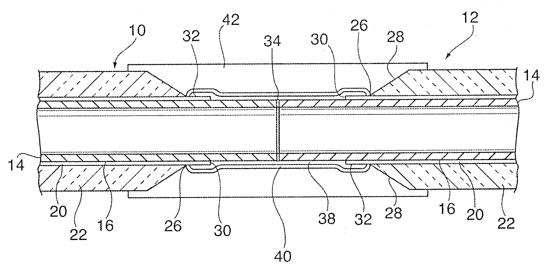
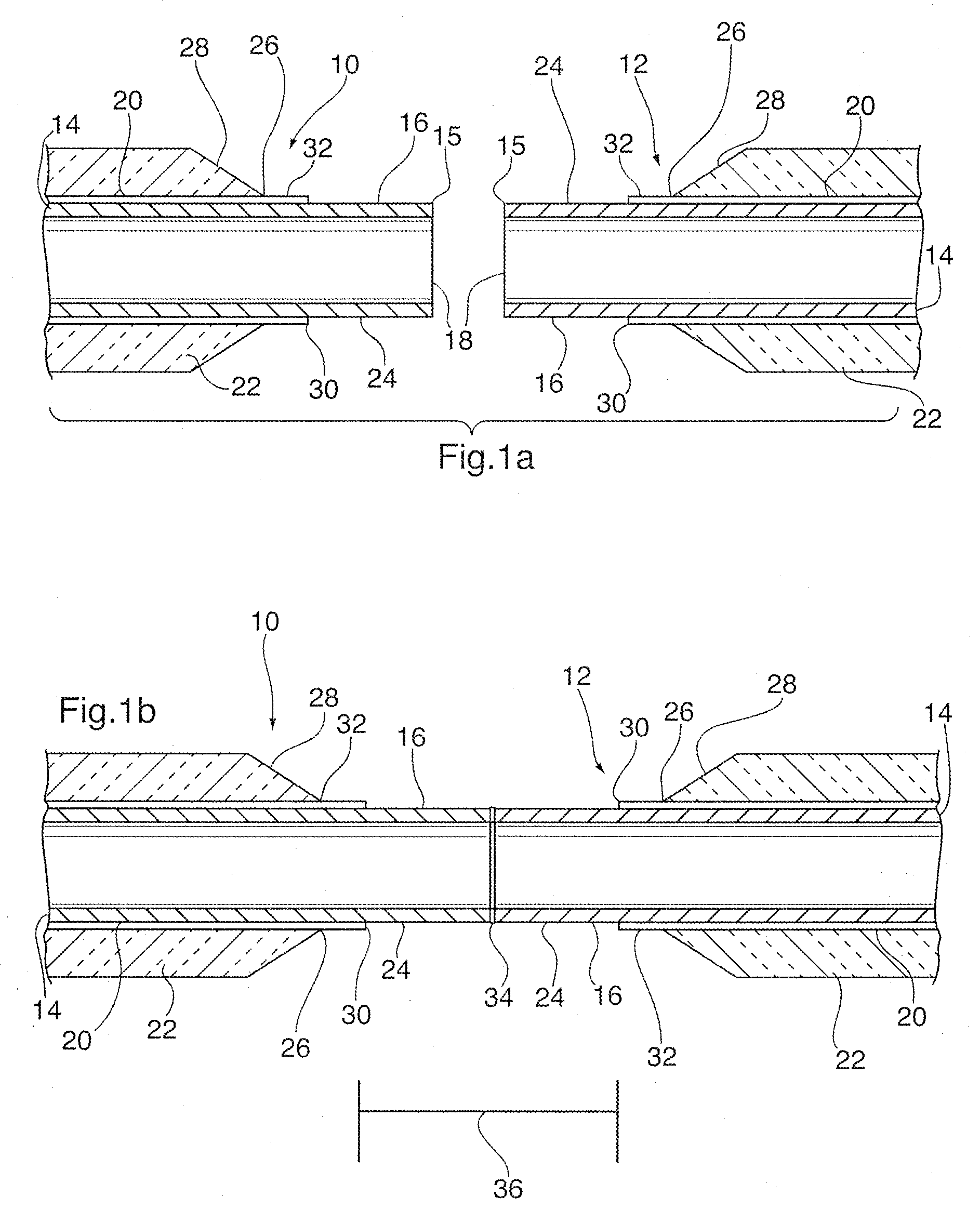
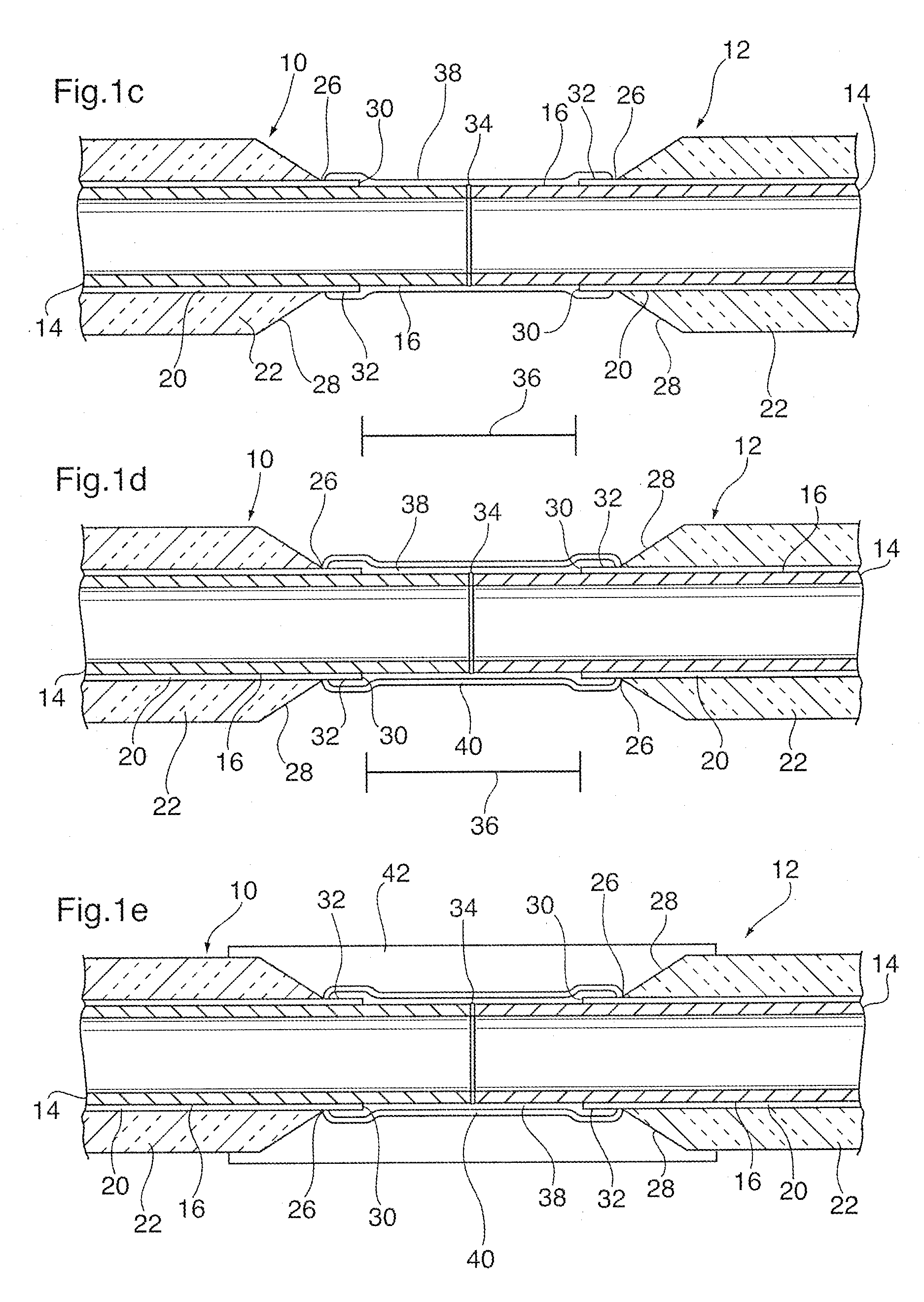
[0082]Two sections of steel pipe were provided, having a nominal wall thickness of 14.3 mm and a nominal diameter of 273.1 cm. The steel pipes each had a factory-applied FBE corrosion protection coating having a glass transition temperature of 105-107 degrees Celsius, a thickness of about 800 micrometers and a polystyrene insulation layer having a thickness of about 55 cm. The corrosion protection coating was provided directly over the outer surface of the steel pipe and the polystyrene insulation layer was provided directly over the corrosion protection coating. The pipe sections had bared end portions about 15 cm in length, with the ends of the insulation layer being chamfered. The corrosion protection coating extended beyond the toe of the chamfer by about 10 mm.

[0083]The bare end portions of the steel pipes were pretreated by blast cleaning to a grade of Sa 2.5, a surface cleanliness rating of 1-2, and a surface roughness Ry (maximum peak-to-valley roughness height) of about 40-...

example 2

[0090]Two sections of steel pipe were provided, having a nominal wall thickness of 14.3 mm and a nominal diameter of 273.1 cm. The steel pipes each had a factory-applied FBE corrosion protection coating having a glass transition temperature of 105-107 degrees Celsius, a thickness of about 800 micrometers and a polypropylene insulation layer having a thickness of about 55 cm. The corrosion protection coating was provided directly over the outer surface of the steel pipe and the polypropylene insulation layer was provided directly over the corrosion protection coating. The pipe sections had bared end portions about 15 cm in length, with the ends of the insulation layer being chamfered. The corrosion protection coating extended beyond the toe of the chamfer by about 10 mm.

[0091]The bare end portions of the steel pipes were pretreated by blast cleaning to a grade of Sa 2.5, a surface cleanliness rating of 1-2, and a surface roughness Ry (maximum peak-to-valley roughness height) of about...


PUM

PropertyMeasurementUnit
Temperatureaaaaaaaaaa

Abstract

A method for forming a field joints between sections of coated or insulated pipe which are to be welded together and incorporated into an undersea pipeline for carrying single or multi-phase fluids such as oil, gas and water. The method includes the application of a liquid epoxy layer which overlaps a lip of the factory-applied FBE coating protruding beyond a chamfered end of the factory-applied insulation layer, and which may be applied over the entire weld joint area. The liquid epoxy layer is partially cured by application of heat, and a layer of powdered adhesive is applied onto the partially cured liquid epoxy layer. The adhesive is subsequently sintered and activated by application of heat to its outer surface. The outer surfaces of the adhesive layer and the chamfers are then preheated and the thermal joint insulation is injection molded over the entire joint area. Throughout the entire method the temperature of the factory-applied FBE coating is maintained below its glass transition temperature so as to avoid weakening the bond between the FBE coating and the underlying steel pipe. The number and sequence of steps can be varied, depending at least partly on whether the liquid epoxy and adhesive layers are applied in a pipe coating facility or in the field.

Description

FIELD OF THE INVENTION[0001]This invention relates to corrosion protection, mechanical protection and insulation of welded joints between sections of coated pipe which are to be incorporated into an undersea pipeline for carrying single or multi-phase fluids such as oil, gas and water.BACKGROUND OF THE INVENTION[0002]Generally speaking, pipelines are formed from sections of steel pipe having factory-applied corrosion protection and insulating coatings. In a typical construction, the pipes are provided with at least two functional layers; an inner corrosion protection coating comprised of for example fusion-bonded epoxy (“FBE”), and an outer layer formed from a thermoplastic such as polypropylene or polyethylene. The insulating layer may be foamed or unfoamed.[0003]In the manufacture of coated / insulated pipe, the ends of the pipe must be left bare so as to prevent damage to the coating when the pipes are joined in the field by welding. Typically, the coating is cut back from the end ...

Claims


Application Information

Patent Timeline
IPC IPC(8): C09J163/00
CPCB29C45/14336B29C45/14598Y10T29/49888F16L58/181F16L59/20B29C2045/14877
Inventor JACKSON, ADAM+527 STBY, GEIR MELVOLDJACKSON, PETER
Owner SHAWCOR LTD
Why Eureka
Try Eureka