
Reduced height pickup truck bed support and method of manufacturing

a pickup truck and support structure technology, applied in the direction of manufacturing tools, roofs, transportation and packaging, etc., can solve the problems of reducing the cargo carrying capacity of the cargo box, the difficulty of persons lifting cargo from the side, etc., to reduce the height required, reduce the center of gravity, and the effect of the same volume of cargo carrying spa

Inactive Publication Date: 2011-12-08
FORD GLOBAL TECH LLC
View PDF0 Cites 44 Cited by
  • Summary
  • Abstract
  • Description
  • Claims
  • Application Information

AI Technical Summary

Benefits of technology

[0008]A pickup truck having an improved cargo box or truck bed support structure reduces the height required for a customer to lift cargo into the pickup truck bed. A reduced height offers advantages for loading the pickup truck from the side or from the rear. In addition, the improved pickup truck bed support structure will lower the center of gravity for the cargo box and its contents while maintaining the same volume of cargo carrying space.
[0009]Some of the benefits of the improved pickup truck bed support structure is that a lower bed floor may be provided and the step up height required for customers to access the cargo box is reduced. Another benefit associated with the improved pickup truck bed support structure is that the center of gravity of the truck may be lowered that in turn improves the static stability factor.

Problems solved by technology

One problem associated with loading a pickup truck bed from the side is that the height of the side wall of the cargo box makes it difficult for persons to lift cargo into the box from the side.
However, reducing the height of the side wall may also reduce the cargo carrying capacity of the cargo box.

Method used


Image

  • Reduced height pickup truck bed support and method of manufacturing
  • Reduced height pickup truck bed support and method of manufacturing
  • Reduced height pickup truck bed support and method of manufacturing

Examples


Embodiment Construction

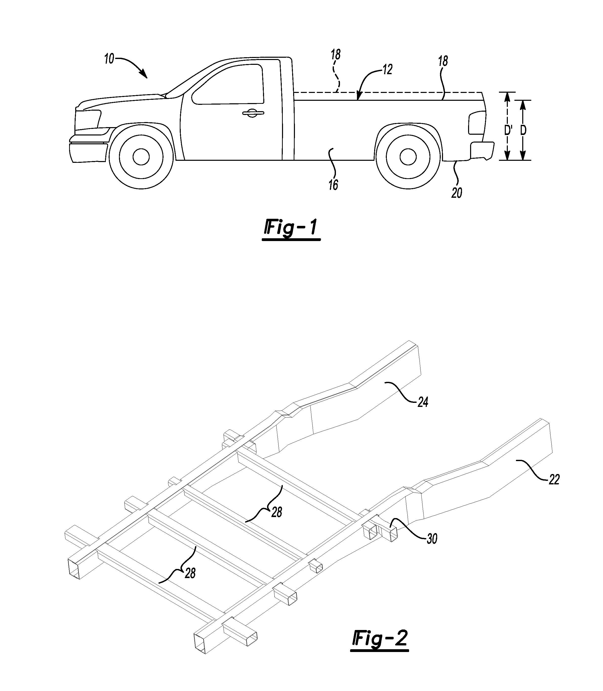
[0029]Referring to FIG. 1, a truck 10, for example a pickup truck, is shown that includes a cargo box 12. The cargo box 12 has a side wall 16 that has a top edge 18. The top edge 18 of the side wall 16 is shown with a lower top edge as compared to the higher top edge 18 shown in phantom lines. The depth of the box indicated by D is measured from the bottom of the chassis 20 to the top edge 18. The depth D′ of a higher profile cargo box 12 is also indicated.

[0030]Referring to FIG. 2, a right frame rail 22 and a left frame rail 24 extend in a longitudinal vehicle direction. Bed frame beams 28 extend in a transverse vehicle direction through the right and left frame rails 22 and 24. One of the frame rails has an additional section and may be referred to as a shock support rail 30.

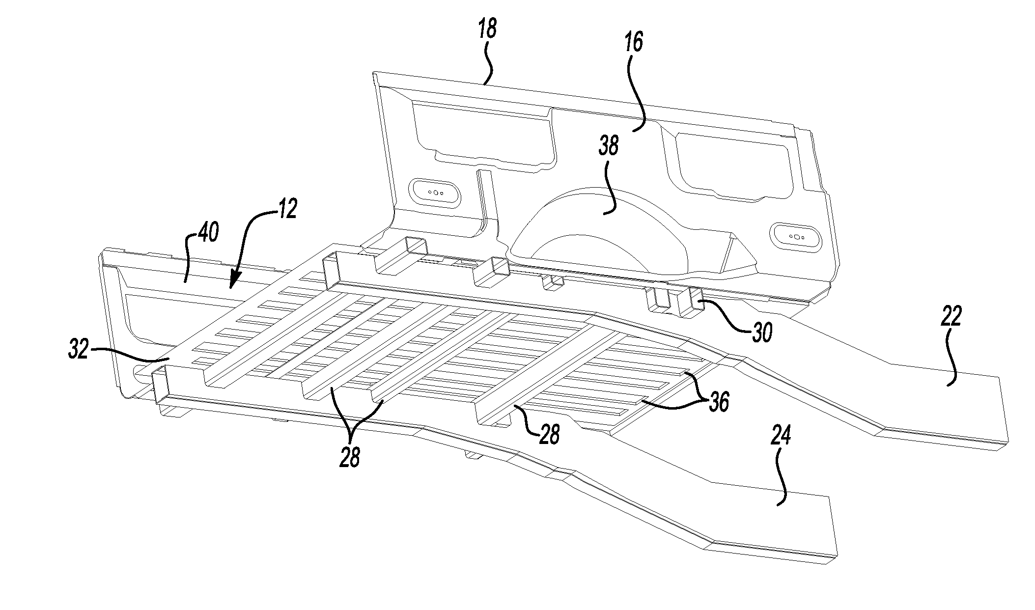
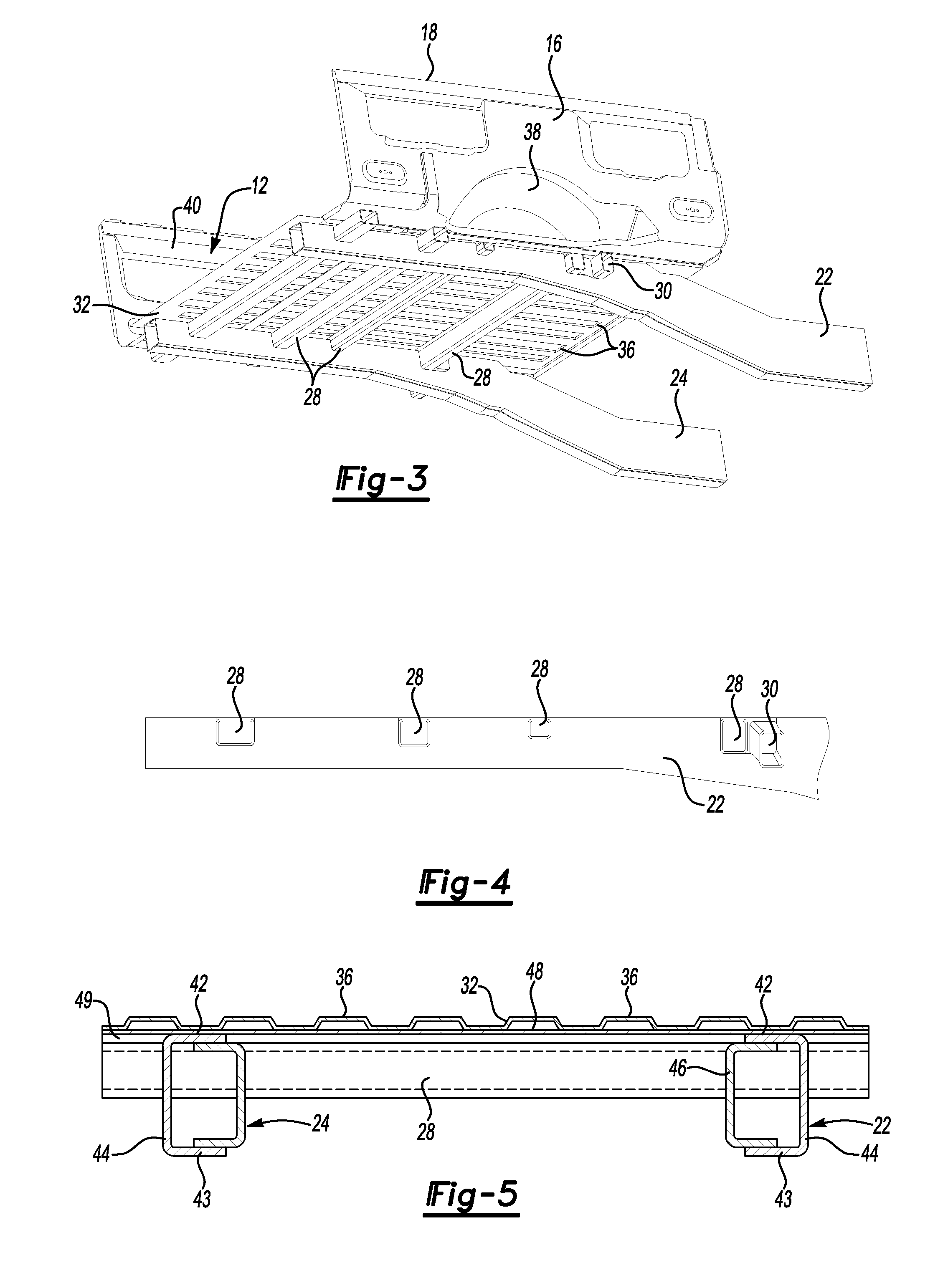
[0031]Referring to FIG. 3, a cargo box 12 is shown assembled to the frame rails 22 and 24 and bed frame beams 28. The truck bed 32 in the bottom of the cargo box 12 is provided with a plurality of stiffening r...


PUM

PropertyMeasurementUnit
Shapeaaaaaaaaaa
Heightaaaaaaaaaa

Abstract

A pickup bed support structure that includes longitudinally extending frame rails to which transversely extending beams used to support the truck bed box are assembled. The beams are received below a top surface of the frame rails by forming notches or holes in the frame rails into which the beams are inserted. Alternatively, notches or holes may be provided in the transversely extending beams that receive the longitudinal extending frame rails. One method of manufacturing a pickup truck bed support structure is disclosed in which holes are provided in the longitudinally extending frame rail that receive the transversely extending beam that support the pickup truck bed. An alternative method is also disclosed in which notches are formed in the frame rails that receive the beams that are welded to the frame rails prior to assembling the pickup truck bed to the beams.

Description

BACKGROUND[0001]1. Technical Field[0002]The present invention relates to a reduced height pickup truck bed support structure and method of manufacturing a pickup truck bed structure.[0003]2. Background Art[0004]Pickup trucks are popular vehicles for work and personal use that have a cargo box including a truck bed that is assembled to the vehicle behind a passenger compartment. Pickup trucks are popular because they can be used to haul cargo conveniently while also offering a comfortable passenger compartment, or pickup truck cab.[0005]Pickup trucks have a cargo box and floor that are closed by a tailgate that is folded down to provide access to the pickup truck box. At times it is preferred to load the pickup truck bed box from the side. One problem associated with loading a pickup truck bed from the side is that the height of the side wall of the cargo box makes it difficult for persons to lift cargo into the box from the side. One way of reducing the height of the side wall of th...

Claims


Application Information

Patent Timeline
IPC IPC(8): B62D25/20B23P11/00
CPCB62D21/03Y10T29/49833B62D33/02B62D25/2054
Inventor JAROCKI, COREY JOHNSAMYN, ANDREW CHARLESSHARKEY, WILLIAMHARMON, MATTHEWHAUSLER, HENRY W.
Owner FORD GLOBAL TECH LLC
Learn More