Integrated circuit comprising frequency generation circuitry for controlling a frequency source

a frequency generation circuit and integrated circuit technology, applied in the direction of automatic control, measurement devices, instruments, etc., can solve the problems of poor vco phase noise, inability to meet system requirements, and inability to completely linearize the voltage to frequency transfer function of a vco

Active Publication Date: 2011-12-08
NXP USA INC
View PDF3 Cites 33 Cited by
  • Summary
  • Abstract
  • Description
  • Claims
  • Application Information

AI Technical Summary

Benefits of technology

[0006]These and other aspects of the invention will be apparent from and elucidated with reference to the examples described hereinafter.

Problems solved by technology

A problem with the use of VCOs is that their frequency characteristics may vary depending on, by way of example, temperature, supply voltage, manufacturing process variations, etc.
Furthermore, the voltage to frequency transfer function of a VCO is not perfectly linear, and the VCO phase noise may be too poor to meet system requirements.

Method used


Image

  • Integrated circuit comprising frequency generation circuitry for controlling a frequency source
  • Integrated circuit comprising frequency generation circuitry for controlling a frequency source
  • Integrated circuit comprising frequency generation circuitry for controlling a frequency source

Examples


Embodiment Construction

[0016]Because the apparatus implementing the present invention is, for the most part, composed of electronic components and circuits known to those skilled in the art, circuit details will not be explained in any greater extent than that considered necessary as illustrated above, for the understanding and appreciation of the underlying concepts of the invention and in order not to obfuscate or distract from the teachings of the present invention.

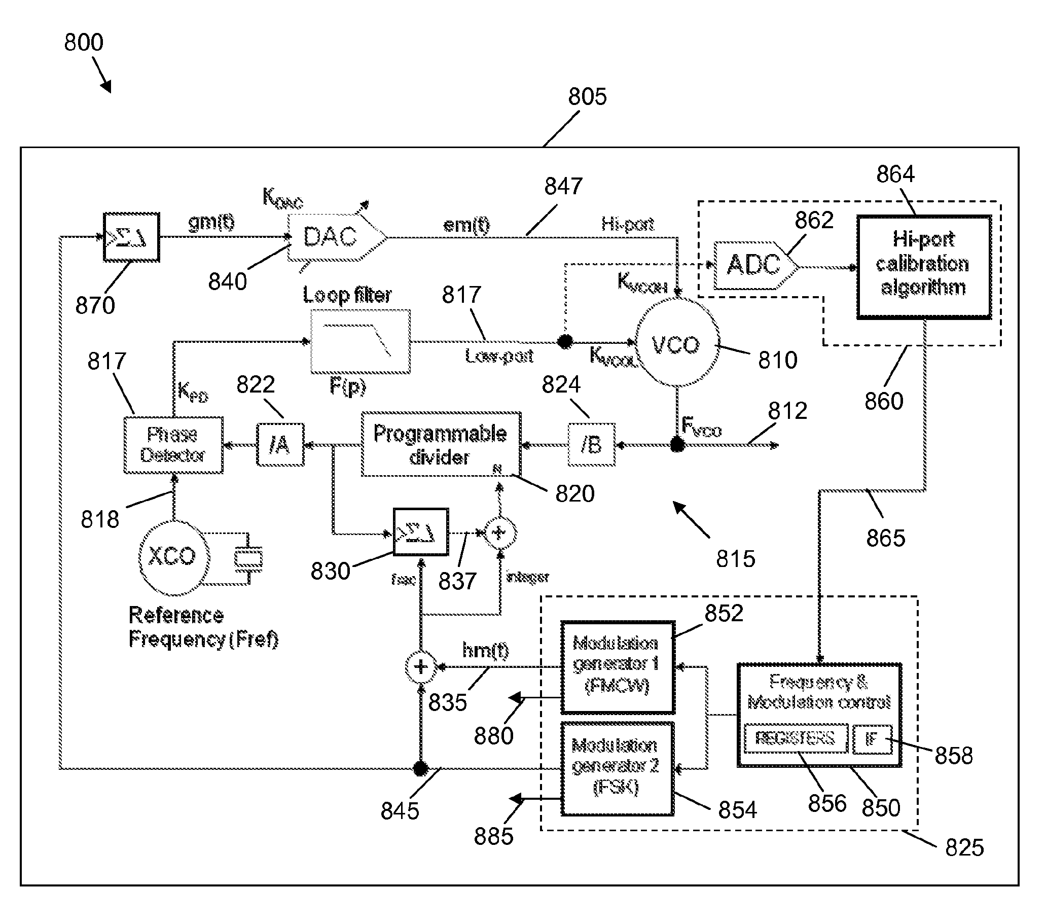
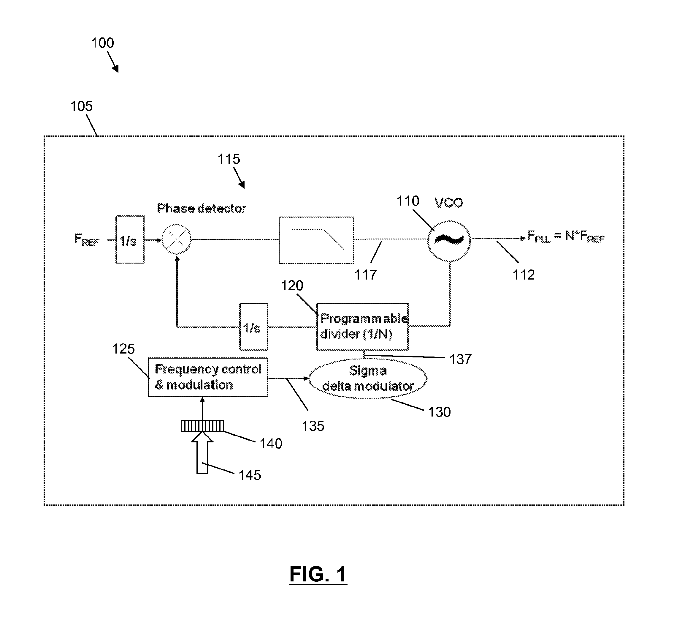
[0017]Referring now to FIG. 1, there is illustrated a first example of frequency generation circuitry 100, comprising a frequency source and control for controlling a frequency for use in an automotive radar system. For the illustrated example, the frequency generation circuitry 100 is provided on an integrated circuit 105. For clarity, the term ‘integrated circuit’ used herein may comprise a single die device, a multi-die device, a single integrated circuit package, multiple integrated circuit packages, etc. It is contemplated that the freq...


PUM


Abstract

An integrated circuit comprises frequency generation circuitry for controlling a frequency source for use in an automotive radar system. The frequency generation circuitry comprises low-path modulation circuitry arranged to generate a first, low-path control signal for providing lower frequency modulation of the frequency source, the low-path modulation circuitry comprising a Phase Locked Loop (PLL) arranged to generate the low-path control signal for controlling the frequency source and a fractional-N divider located within a feedback loop of the PLL, and frequency pattern control module operably coupled to the fractional-N divider and arranged to control the fractional-N divider, by way of at least a first, lower frequency pattern control signal. The frequency generation circuitry further comprises high-path modulation circuitry arranged to generate a second, high-path control signal for providing higher frequency modulation of the frequency source.

Description

FIELD OF THE INVENTION[0001]The field of the invention relates to frequency generation circuitry for controlling a frequency source, and in particular to frequency generation circuitry for controlling a frequency source for an automotive radar system.BACKGROUND OF THE INVENTION[0002]In the automotive industry, it is known to provide vehicles with radar systems. For example a short range radar system may be provided to aid a driver of the vehicle in determining a distance between the vehicle and nearby objects, such as other vehicles during, say, a parking manoeuvre or the like. Additionally, a longer range radar system may be provided for use with an adaptive cruise control system, whereby the cruise control system maintains a substantially constant distance between the vehicle in which the system is provided and a vehicle in front. Typically, such an automotive radar system comprises a transmitter for transmitting a carrier signal within a given frequency band, for example within a...

Claims


Application Information

Patent Timeline
Patent Type & Authority Applications(United States)
IPC IPC(8): H03L7/08
CPCG01S7/032G01S7/35G01S13/34G01S2013/9325H03C3/0925H03L7/1976G01S13/931
Inventor SALLE, DIDIERDOARE, OLIVIERDUGALLEIX, STEPHANE
Owner NXP USA INC
Why Eureka
Try Eureka