Self dynamo smart flow utility meter and system for flow utility real-time flow usage monitoring and control, self error and leakages monitoring

Inactive Publication Date: 2011-12-08
YIP BERNIE
View PDF25 Cites 19 Cited by
  • Summary
  • Abstract
  • Description
  • Claims
  • Application Information

AI Technical Summary

Benefits of technology

[0015]As mention above, the central server could receive all flow usage data in its network real-time. Therefore, all flow usage data could record into its database. The invention includes a web based user interface. End users could register their daily regular flow usage and their personal information such as phone number and email address into the database. The central server could compare their registered daily information and the real-time usage level. If the real-time usage level shows a dangerous level, the central server sends out an alert to the end user with internet

Problems solved by technology

Such a method is very time consuming and, thus, costly.
Additionally, there is a chance workers may incorrectly read one or more meters thereby providing incorrect data to utility company.
However, they all could NOT provide REAL-TIME flow usage data, self error diagnostic, self leakage detection and remote flow rate control capabilitie

Method used


Image

  • Self dynamo smart flow utility meter and system for flow utility real-time flow usage monitoring and control, self error and leakages monitoring
  • Self dynamo smart flow utility meter and system for flow utility real-time flow usage monitoring and control, self error and leakages monitoring
  • Self dynamo smart flow utility meter and system for flow utility real-time flow usage monitoring and control, self error and leakages monitoring

Examples


Embodiment Construction

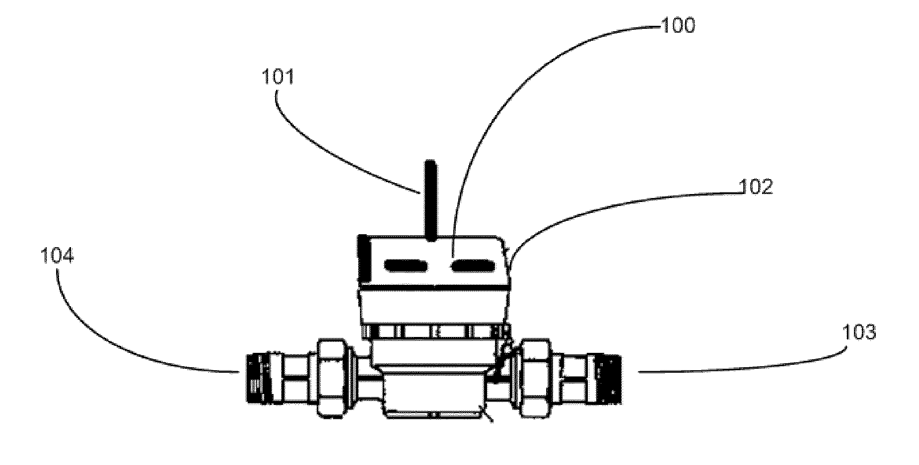
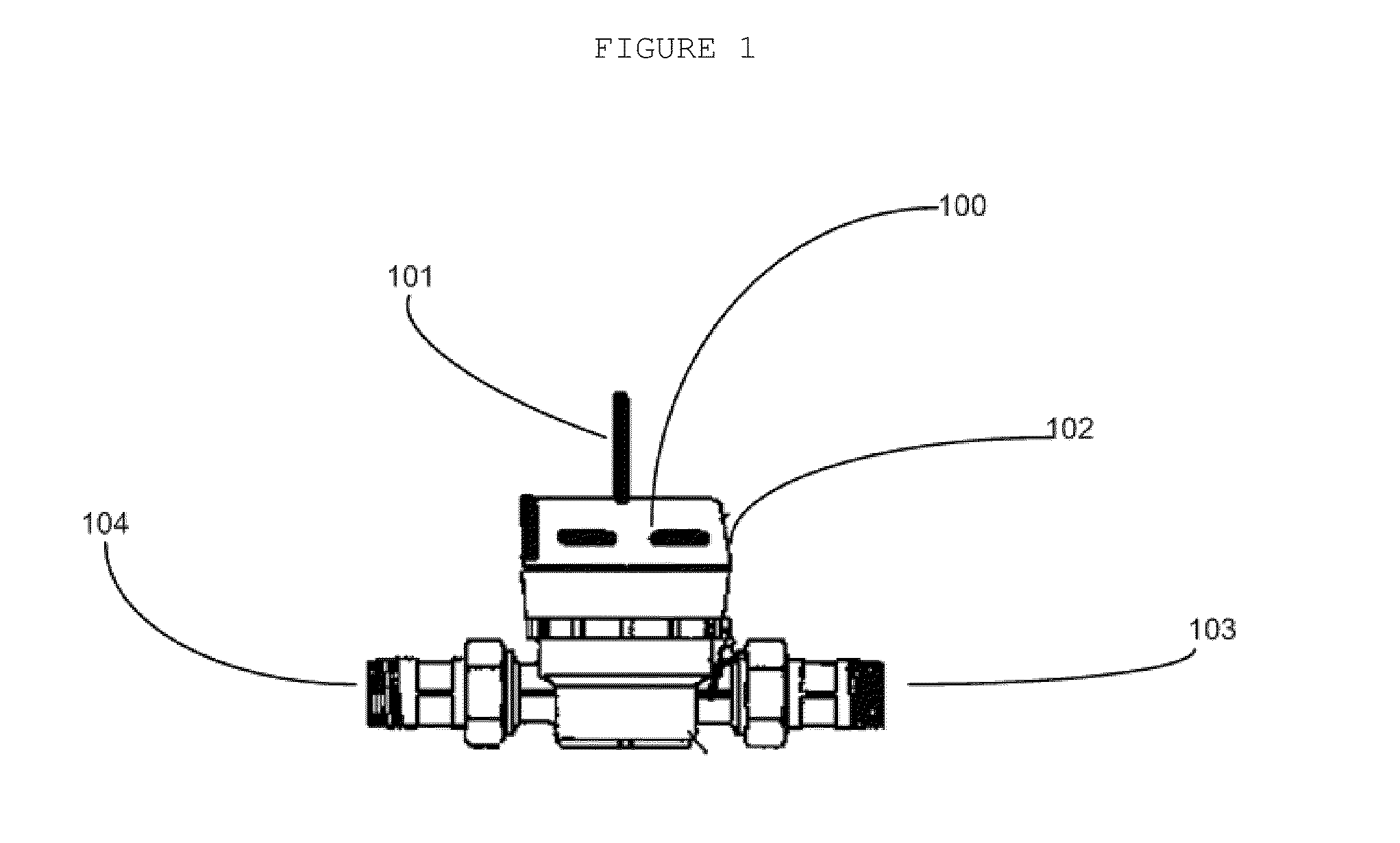
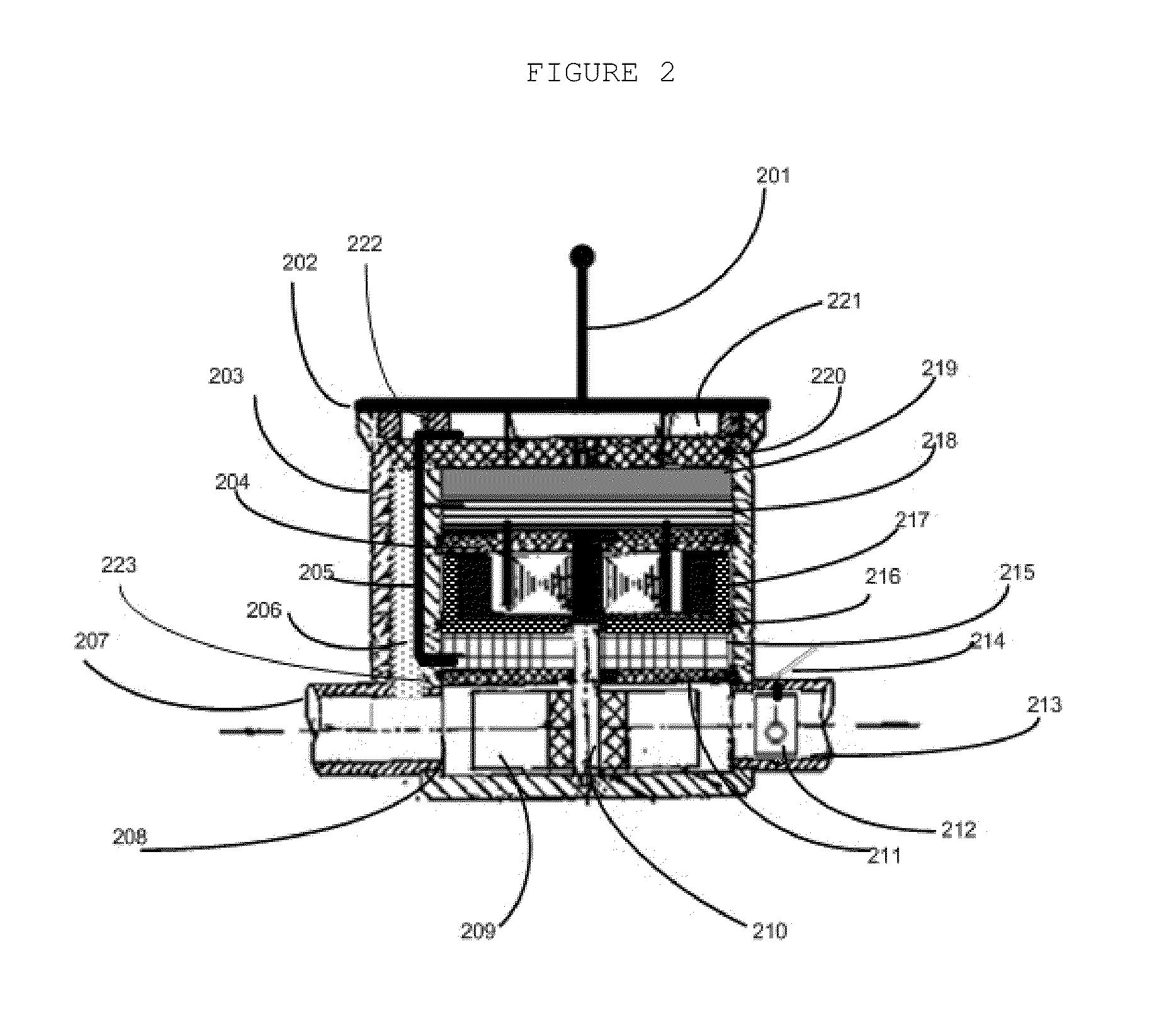
[0029]A front view of a self dynamo smart flow utility meter is shown in FIG. 1. The description and operation of the self dynamo smart flow meter invention will be best initiated with reference to FIG. 2. Most of self dynamo smart flow meter components are inside of the external housing chamber 203. The antenna 201 is physically connected to a cover 202 and the antenna 201 wire is connected to the smart electric circuit 218. On the top of the smart electric circuit 218 is the electric energy storage, battery 219, on the top of battery 219, is the thermal baffle plate 220 which isolates the display 221 and rest of the components under it. The electric energy storage unit 219 is right under the thermal baffle plate 220. The display power input and control signal is connected to the smart electric circuit 218 through the signal tunnel 205. The display only will be activated when the cover 202 open by released the on / off switches 222. Under the smart electric circuit 218, is other baff...


PUM


Abstract

A self dynamo smart flow utility meter providing self electric energy, real-time wireless data transmission ability and remotely flow control ability is disclosed. Also, a method and system for flow utility real-time flow usage monitoring and control, self error diagnostic and self leakage monitoring is disclosed.

Description

RELATED APPLICATIONS[0001]The present application is a continuation application of U.S. provisional patent application, Ser. No. 61 / 351,813, filed Jun. 4, 2010, included by reference herein and for which benefit of the priority date is hereby claimed.FIELD OF THE INVENTION[0002]This invention relates to a flow utility meter which provides self dynamo ability, real-time wireless data transmit ability and remote control abilities. Furthermore, the invention relates to a system and method provides real-time remote reading flow utility usage ability, self error diagnostic ability, self leakage detection ability and automatically remote control self dynamo smart flow meter within its network.BACKGROUND OF THE INVENTION[0003]Traditionally, utility company has to employ “meter readers” to visit each customer location or home and take the reading, by visually observing the meter and recording in tabulated form a hand-written record of the utility consumption and the corresponding customer. ...

Claims


Application Information

Patent Timeline
IPC IPC(8): G08B21/00
CPCG01F25/0007G01D21/00G01F15/063G01F15/00G01F1/06G01F25/10
Inventor YIP, BERNIE
Owner YIP BERNIE
Why Eureka
Try Eureka