Optical slicer for improving the spectral resolution of a dispersive spectrograph

a technology of optical spectrograph and spectrograph, which is applied in the field of optical slicer for improving the spectral resolution of dispersive spectrograph, can solve the problems of limiting the performance of optical spectrograph, signal-to-noise ratio, and reducing the quality of any measuremen

Active Publication Date: 2011-12-08
TORNADO SPECTRAL SYST
View PDF6 Cites 57 Cited by
  • Summary
  • Abstract
  • Description
  • Claims
  • Application Information

AI Technical Summary

Problems solved by technology

By narrowing the width of the input slit, less light passes therethrough, which can reduce the quality of any measurements due to a reduction in the signal-to-noise ratio.
In some applications, such as astronomical spectroscopy, high-speed biomedical spectroscopy, high-resolution spectroscopy, or Raman spectroscopy, this loss of efficiency can be a limiting factor in the performance of the optical spectrograph.
The use of transparent prisms and plates to slice an input beam can produce a slit that is tilted along the optical axis, and additionally the slicing of an optical beam can occur along the hypotenuse of a 45° prism, which can result in focal point degradation due to different sections of the sliced image being located at different focal positions.
These deficiencies can limit the use of such slicers as broadband devices.
Other slicers, such as pupil slicers, possess drawbacks such as the inability to obtain high-resolution spectral information from different portions of an image.
Additionally, such slicers can be large in size, ...

Method used


Image

  • Optical slicer for improving the spectral resolution of a dispersive spectrograph
  • Optical slicer for improving the spectral resolution of a dispersive spectrograph
  • Optical slicer for improving the spectral resolution of a dispersive spectrograph

Examples


Embodiment Construction

[0034]It will be appreciated that for simplicity and clarity of illustration, where considered appropriate, reference numerals may be repeated among the figures to indicate corresponding or analogous elements or steps. In addition, numerous specific details are set forth in order to provide a thorough understanding of the embodiments described herein. However, it will be understood by those of ordinary skill in the art that the embodiments described herein may be practiced without these specific details. In other instances, well-known methods, procedures, and components have not been described in detail so as not to obscure the embodiments described herein. Furthermore, this description is not to be considered as limiting the scope of the embodiments described herein in any way, but rather as merely describing the implementation of the various embodiments described herein.

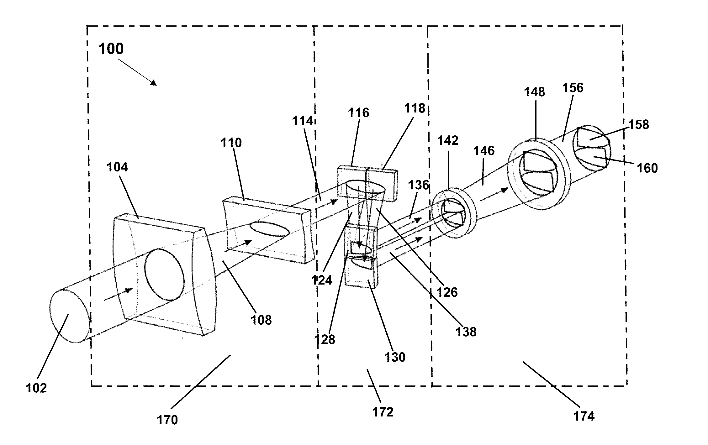
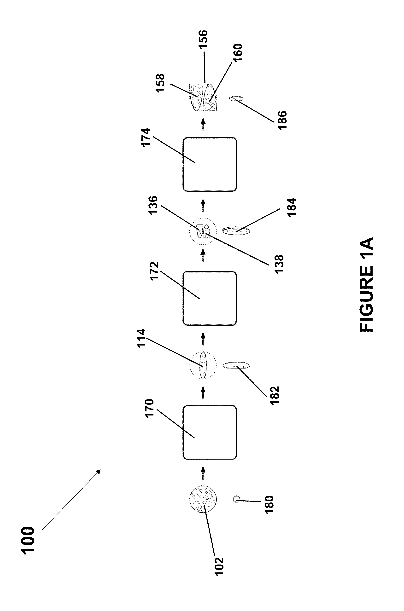
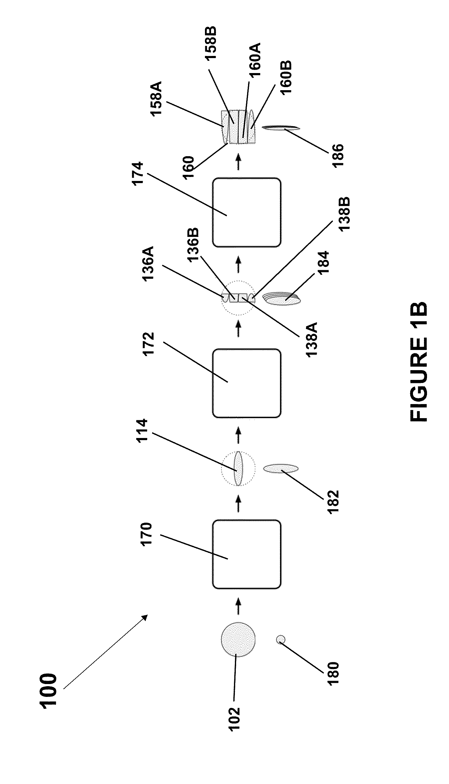
[0035]With reference to FIG. 1A, a representation of optical slicer 100 is shown, optical slicer including image...


PUM


Abstract

An optical slicer for generating an output spot comprising an image compressor which receives a substantially collimated input beam and compresses the beam, wherein the input beam, if passed through a focusing lens, produces an input spot; an image reformatter which receives the compressed beam to reformat the beam into a plurality of sliced portions of the compressed beam and vertically stacks the portions substantially parallel to each other; and an image expander which expands the reformatted beam to produce a collimated output beam which, if passed through the focusing lens, produces the output spot that is expanded in a first dimension and compressed in a second dimension relative to the input spot.

Description

RELATED APPLICATIONS[0001]This application claims priority from U.S. Provisional Application No. 61 / 245,762 filed Oct. 1, 2009 and U.S. Provisional Application No. 61 / 350,264 filed Jun. 1, 2010, the contents of each of which are herein incorporated by reference.FIELD OF INVENTION[0002]This invention relates to the field of spectroscopy and more specifically relates to improved apparatus and methods for improving spectral resolution.BACKGROUND[0003]A typical optical spectrograph includes a small input aperture, typically a slit, however, can alternatively be a circular pinhole or an optical fiber; however, for the sake of brevity, will hereinafter be referred to as a slit. A converging cone of light, is projected towards the slit and a portion of the light passes through the slit. In a typical optical spectrograph, this slit of light is projected onto a lens which collimates the slit of light to form a beam of parallel light rays. In a typical optical spectrograph, a dispersive eleme...

Claims


Application Information

Patent Timeline
IPC IPC(8): G01J3/28G02B27/14G02B27/10
CPCG01J3/02G01J3/0202G01J3/0205G02B27/10G02B27/0927G02B27/0955G01J3/021
Inventor MEADE, JEFFREY T.HAJIAN, ARSEN R.BEHR, BRADFORD B.CENKO, ANDREW T.
Owner TORNADO SPECTRAL SYST
Why Eureka
Try Eureka