Eureka AIR delivers breakthrough ideas for toughest innovation challenges, trusted by R&D personnel around the world.

Digital dynamic delay modulator and the method thereof for flyback converter

Active Publication Date: 2011-12-08
POWER FOREST TECH
View PDF5 Cites 6 Cited by
  • Summary
  • Abstract
  • Description
  • Claims
  • Application Information

AI Technical Summary

Benefits of technology

[0010]It is an object of the present invention to provide a digital dynamic delay modulator for flyback converter, whereby the delay time for switching the flyback converter can be precisely controlled in digital and dynamic manner.
[0011]It is another object of the present invention to provide a digital dynamic delay modulating method for flyback converter, whereby the delay time for switching the flyback converter can be precisely controlled in digital and dynamic manner.

Problems solved by technology

However, the mass-produced QR flyback converters have difficulty to achieve soft switching at valley voltage of the switching device; therefore, the efficiency of the mass-produced QR flyback converters cannot be guaranteed.
Therefore, switching device Q cannot be precisely switched at the resonant valley.
However, the control circuits of the mass-produced QR flyback converters generally have different propagation delays, and the constant delay time cannot switch all of the mass-produced QR flyback converters at the resonant valley.
It is inevitable for the time delay TDLY to have analog error.
More particularly, current source 230 with variable and precise current range is difficult to realize.
The above-mentioned analog error factors are aggravated for advanced manufacture process, and this makes circuit design more difficult.

Method used


Image

  • Digital dynamic delay modulator and the method thereof for flyback converter
  • Digital dynamic delay modulator and the method thereof for flyback converter
  • Digital dynamic delay modulator and the method thereof for flyback converter

Examples


Embodiment Construction

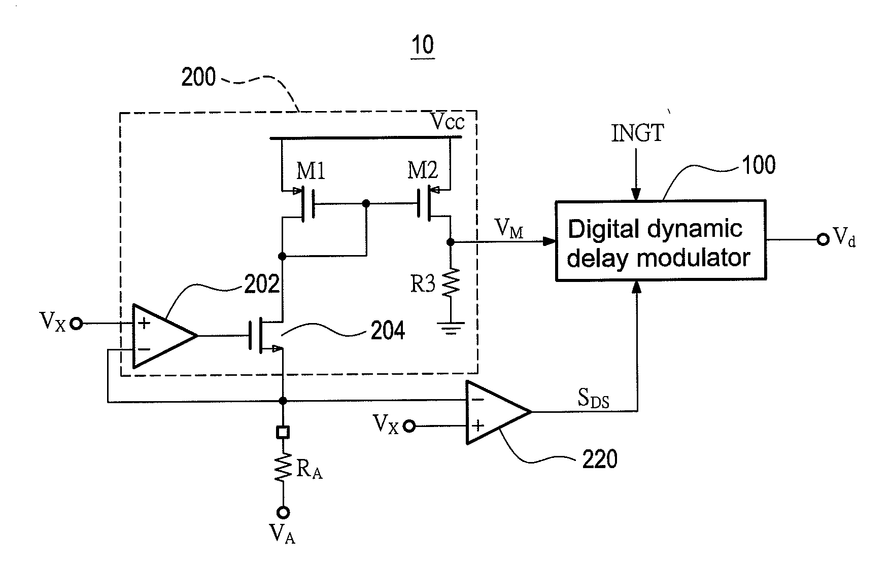
[0024]FIG. 6 shows the schematic view of the digital dynamic delay modulator 100 for flyback converter according to a preferred embodiment of the present invention. The digital dynamic delay modulator 100 of the present invention can be built in a controller chip of a flyback converter, where the controller chip is electrically connected to an auxiliary winding NA of a transformer and a switching device Q1. The digital dynamic delay modulator 100 controls the gate voltage for the switching device Q1 according to an extreme value (peak value or valley value) of the voltage signal VA on the auxiliary winding NA, or other signal replica. The controller chip of the flyback converter further comprises other components such as feedback control unit and switch controller for generating the gate voltage for the switching device Q1. Those components are well known to those skilled in the related art, and the detailed descriptions thereof are omitted here for brevity.

[0025]FIG. 7 is a schemat...


PUM


Abstract

A digital dynamic delay modulator and the method thereof are applied to a flyback converter. A first input voltage signal from the flyback converter is received and compared with a threshold voltage to determine whether a counting condition is matched. When the counting condition is matched, an integer predetermined count number is counted to determine a delay time. After finishing the counting, a first output signal is generated to turn on a switching device for the flyback converter. The slope of the first input voltage signal is detected when the switching device is turned on, and the slope is used to adjust the count number with integer increment / decrement. Therefore, the delay time for switching the flyback converter can be precisely controlled in digital and dynamic manner.

Description

BACKGROUND OF THE INVENTION[0001]1. Field of the Invention[0002]The present invention relates to power electronics, especially to an apparatus and a method for precise valley detection in quasi-resonant (QR) flyback converters.[0003]2. Description of Prior Art[0004]Flyback converters are extensively employed in low-power conversion applications due to the advantages of low cost and simple architecture. More specifically, quasi-resonant (QR) flyback converters can enhance the system performance without increasing system complexity and elements used. Therefore, QR flyback converters are advantageous in economic and environmental aspects.[0005]FIG. 1 shows a schematic view of a prior art QR flyback converter. FIG. 2 shows the signal waveforms relevant to the operation of the QR flyback converter in FIG. 1. After energy is fully discharged from the secondary winding Ns, a resonant is established by a resonant tank consisting of the magnetizing inductor of the primary winding Np and the ...

Claims


Application Information

Patent Timeline
IPC IPC(8): H02M3/335
CPCH02M3/33515
Inventor TZENG, REN-HUEILI, JAN-HE
Owner POWER FOREST TECH
Why Eureka
Eureka Blog
Learn More