Systems and methods for reliable multi-level cell flash storage

a multi-level cell and flash storage technology, applied in the field of flash memory, can solve the problems of unperceivable by the end user, unreliable, and unwanted transitions in the logical state of the cell,

Active Publication Date: 2011-12-08
SYNAPTICS INC
View PDF5 Cites 82 Cited by
  • Summary
  • Abstract
  • Description
  • Claims
  • Application Information

AI Technical Summary

Benefits of technology

An electronic device such a digital camera, a printer, a multi-function peripheral, a scanner, a music player, a portable video game, a camcorder, a digital picture frame, a cellular telephone, or a combination thereof, comprising a processing unit, MLC flash memory and a memory controller. The MLC flash memory comprises a a critical portion and can further comprise a non-critical portion. Each memory cell in the critical portion of the MLC flash memory is mapped to a single binary value. If the memory cell is in an MLC having a threshold voltage greater than a cutoff threshold voltage, the value read is interpreted as a high binary value. Otherwise, the value read is interpreted as a low binary value.

Problems solved by technology

The reliability, however, is often lower because the adjacent voltage levels used to represent different voltage levels are closer together, so charge leaking to or from a control gate can result in an unwanted transition in the logical state of the cell.
For media applications a small amount of error is generally acceptable and may even be unperceivable by the end user.
For example, an incorrect bit or bits in a movie could result in a block being distorted or in a song could result in an inaudible pop.
However, for firmware applications and especially boot ROM applications, a bit error would mean an incorrect instruction would be read from flash causing the firmware to malfunction.
The use of two different types of flash, each likely requiring its own memory controller, increases the cost, size and complexity of the electronic device.

Method used


Image

  • Systems and methods for reliable multi-level cell flash storage
  • Systems and methods for reliable multi-level cell flash storage
  • Systems and methods for reliable multi-level cell flash storage

Examples


Embodiment Construction

A detailed description of embodiments of the present invention is presented below. While the disclosure will be described in connection with these drawings, there is no intent to limit it to the embodiment or embodiments disclosed herein. On the contrary, the intent is to cover all alternatives, modifications and equivalents included within the spirit and scope of the disclosure.

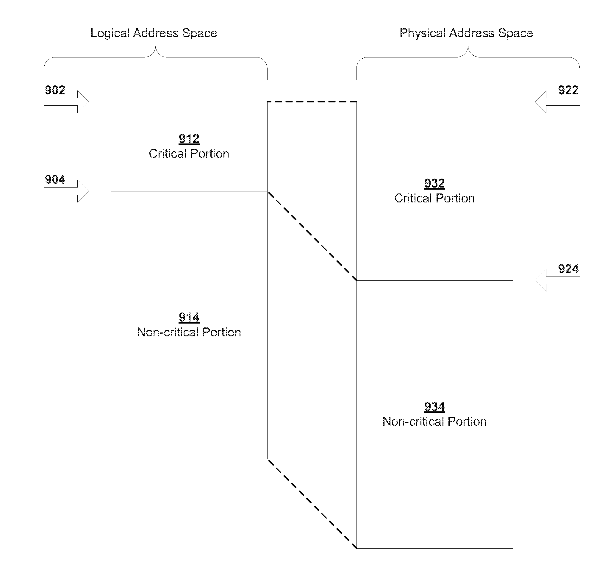
In an embodiment of the present invention, an MLC storage device is converted into high reliability storage by storing a single binary value to each cell in an MLC. The entire MLC storage device can be converted or a portion. In the former case, MLC memory could be more available or much cheaper than SLC memory so the MLC memory could be used in place of SLC memory. In the latter case an electronic device can be partitioned into a critical portion for storing critical data such as firmware and a non-critical portion for storing non-critical but potentially higher capacity data such as media.

In a preferred em...


PUM


Abstract

Multi-level cell (MLC) flash memory has become widely used due to their capacity to store more information in the same area as a single-level cell (SLC) flash memory. This makes MLC flash memory very attractive for storing media. Flash has also traditionally been used in electronic devices for firmware, but MLC flash is less reliable than SLC flash. For critical memory operations, MLC flash memory can be made as reliable as SLC flash by mapping one binary value to an MLC state corresponding to the highest threshold voltage and the other binary value to the MLC state corresponding the lowest threshold voltage when writing to the MLC flash, and by mapping all MLC states with corresponding threshold voltages above a central cutoff threshold voltage to one binary value and by mapping all MLC states with corresponding threshold voltages below a central cutoff threshold voltage to the other binary value.

Description

TECHNICAL FIELDThe present invention relates generally to flash memory and more specifically to flash memory with robust use of multi-level cells.BACKGROUND OF THE INVENTIONFlash memory is a non-volatile computer memory that can be electrically erased and reprogrammed. It is a specific type of EEPROM (Electrically Erasable Programmable Read-Only Memory) that is erased and programmed in large blocks. It derives its name from the early days when the entire chip had to be erased at once, a “flash erase.” Due to its low cost compared to both other forms of EEPROMs or battery-powered random access memory (RAM), flash memory has become a dominant technology when non-volatile, solid state storage is need.Originally, the main application of flash memory was to store firmware for a computer or electronic device. The non-volatility makes it suitable for storing critical software, including boot code, and the reprogrammability gives it the flexibility to accept firmware changes. Many devices w...

Claims


Application Information

Patent Timeline
Patent Type & Authority Applications(United States)
IPC IPC(8): G06F12/00G06F12/02G11C16/04
CPCG11C11/5642G11C2211/5641G11C16/22
Inventor MILLER, MARK E.
Owner SYNAPTICS INC
Why Eureka
Try Eureka