Weight/sensor-controlled sorbent system for hemodialysis

a sorbent system and sensor technology, applied in the field of dialysis systems, can solve the problems of inability to balance water, minerals and excretion of daily metabolic load, inability to excrete daily metabolic load, and inability to achieve the balance of water, minerals and excretion, etc., to achieve the effect of improving the system and method of dialysis and improving the quality of li

Inactive Publication Date: 2011-12-15
BAXTER INT INC +1
View PDF4 Cites 57 Cited by
  • Summary
  • Abstract
  • Description
  • Claims
  • Application Information

AI Technical Summary

Benefits of technology

One advantage of the present invention is to provide improved systems and methods for performing dialysis.
is to provide improved systems and methods for performing dialysis.
Another advantage of the present invention is to provide improved systems and methods for performing automated continuous flow dialysis systems and methods.
A further advantage of the present invention is to provide regenerative dialysis systems and methods of operating same.
Still another advantage of the present invention is to provide a regenerative dialysis system that has clinical advantages.
Still a further advantage of the present invention is to provide a regenerative dialysis system that has economic advantages.

Problems solved by technology

Due to disease, insult or other causes, a person's renal system can fail.
The balance of water, minerals and the excretion of daily metabolic load is no longer possible in renal failure.
During renal failure, toxic end products of nitrogen metabolism (urea, creatinine, uric acid, and others) can accumulate in blood and tissues.
Consequently, contamination of such a dialysis system can be a concern.
Further, the dialysate fluid exiting the REDY™ cartridge is not suitable for peritoneal dialysis because the fluid is relatively acidic and not, therefore, physiologic.
Moreover, this system requires the attention of medical personnel during therapy.
Manual peritoneal dialysis performed by the patient requires a significant amount of time and effort from the patient.
This inconvenient procedure leaves ample room for improvement and therapy enhancements to improve patient quality of life.
However, these systems typically have a single pass fluid flow.
That is, the systems have no ability to regenerate or reuse a quantity of dialysate.

Method used


Image

  • Weight/sensor-controlled sorbent system for hemodialysis
  • Weight/sensor-controlled sorbent system for hemodialysis
  • Weight/sensor-controlled sorbent system for hemodialysis

Examples


Embodiment Construction

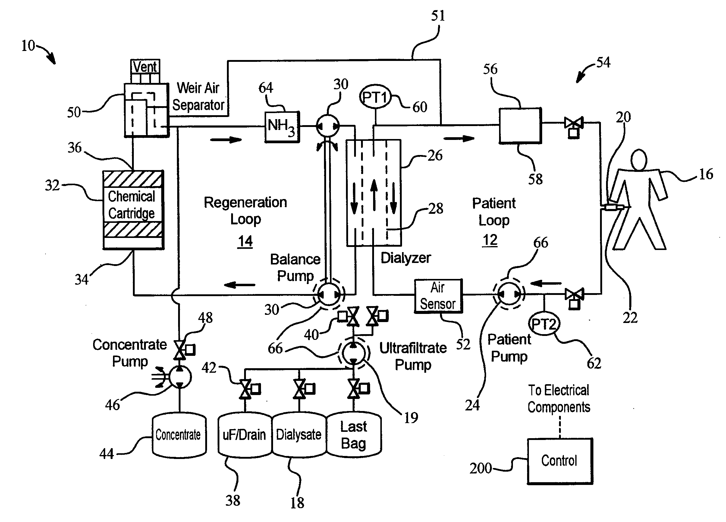
Generally, the present invention relates to dialysis systems and methods of performing dialysis. In an embodiment, the present invention pertains to continuous flow regeneration peritoneal dialysis systems and methods. In other embodiments the present invention pertains to non-continuous flow regeneration peritoneal dialysis, and regeneration hemodialysis, both continuous and non-continuous flow.

The dialysis system automatically performs dialysis therapy on a patient, for example during nighttime while the patient sleeps. The present invention can provide true continuous flow dialysis therapy (fluid simultaneously flowing into and out of the patient), and automatically regenerate spent dialysate into fresh dialysate that is again used for the dialysis treatment. Continuous flow of dialysate tends to increase the efficacy of treatment by maximizing or maintaining a maximum osmotic gradient across the peritoneal membrane. Regeneration of dialysate by the present invention significantl...


PUM


Abstract

A hemodialysis system including (i) a dialyzer; (ii) a blood circuit including a blood pump in fluid communication with the dialyzer; (iii) a dialysate circuit including a dialysate circulation pump in fluid communication with the dialyzer, the dialysate circuit further including a sorbent cartridge for cleaning used dialysate; (iv) a container holding an initial supply of dialysate; (v) a container pump in fluid communication with the dialysate circuit and the container; (vi) a supply of concentrate; and (vii) an electronic weight balance positioned and arranged to weigh the supply of concentrate.

Description

BACKGROUNDThe present invention generally relates to dialysis systems. More specifically, the present invention relates to regeneration dialysis systems and continuous flow dialysis systems. The present invention also relates to methods of performing dialysis therapies.Due to disease, insult or other causes, a person's renal system can fail. In renal failure of any cause, there are several physiological derangements. The balance of water, minerals and the excretion of daily metabolic load is no longer possible in renal failure. During renal failure, toxic end products of nitrogen metabolism (urea, creatinine, uric acid, and others) can accumulate in blood and tissues.Kidney failure and reduced kidney function have been treated with dialysis. Dialysis removes waste, toxins and excess water from the body that would otherwise have been removed by normal functioning kidneys. Dialysis treatment for replacement of kidney functions is critical to many people because the treatment is life s...

Claims


Application Information

Patent Timeline
Patent Type & Authority Applications(United States)
IPC IPC(8): B01D61/26B01D61/34A61M1/14A61M1/16A61M1/28
CPCA61M1/1656A61M1/1696A61M1/28A61M1/1658A61M2205/12A61M1/284A61M1/288A61M1/287A61M1/285
Inventor CHILDERS, ROBERT W.BROWN, DAVID S.WARIAR, RAMESHKAROOR, SUJATHADIN, SHAHIDMARTIS, LEOBUCHMANN, CODYSOLTYS, PAUL
Owner BAXTER INT INC
Why Eureka
Try Eureka