
Phase difference enhanced imaging method (PADRE), functional image creating method, phase difference enhanced imaging program, phase difference enhanced imaging apparatus, functional image creating apparatus, and magnetic resonance imaging (MRI) apparatus

a phase difference and enhanced imaging technology, applied in the field of phase difference enhanced imaging methods, can solve the problems of difficult flexibly responding to the change in phase difference distribution by the exponent, preventing secure enhancement of objective tissue, and affecting the accuracy of image enhancement, etc., to achieve accurate display of activated region, secure enhancement of objective tissue, and high spatial resolution

Active Publication Date: 2011-12-15
NATIONAL UNIVERSITY
View PDF5 Cites 10 Cited by
  • Summary
  • Abstract
  • Description
  • Claims
  • Application Information

AI Technical Summary

Benefits of technology

[0007]The present invention is made to solve the above-described issue, and it is a first object to provide a phase difference enhanced imaging method, a phase difference enhanced imaging program, a phase difference enhanced imaging apparatus, and a magnetic resonance imaging apparatus, which enable secure enhancement of an objective tissue even if an imaging site or an imaging condition is changed. In addition, it is a second object to provide a functional image creating method and a functional image creating apparatus, enabling rendering of an activated region using the phase difference enhanced imaging method.
[0014]In the phase difference enhanced imaging method, the phase difference enhanced imaging program, the phase difference enhanced imaging apparatus, and the magnetic resonance imaging apparatus according to the invention, a phase corresponding to an objective tissue in a phase difference image created using a first complex image and a second complex image is selected taking account of change in distribution of phase difference due to filtering. This makes it possible to optionally select a phase corresponding to a tissue to be desirably provided with contrast. In addition, an exponential function is selected as an enhancement function for enhancing the selected phase. This, for example, makes it possible to approximate an optional power function with optional accuracy, enabling flexible response to change in distribution of phase difference.
[0021]In the first functional image creating method and the first functional image creating apparatus according to the invention, the first function signal image is created by enhancing, by the enhancement function, a difference (phase difference variation) between the first phase difference image in the inactive state created using the third and fifth complex images and the second phase difference image in the active state created using the fourth and sixth complex images. This makes it possible to reflect the BOLD (Blood Oxygen Level Dependent) effect induced by an activated tissue, and besides to distinguish a signal caused by entering of blood flow (for example, a signal due to a two-dimensional effect caused by activation of a tissue in a large blood vessel other than a capillary vessel). In addition, an exponential function is selected as an enhancement function in the invention. This, for example, makes it possible to approximate an optional power function with optional accuracy, enabling flexible response to change in distribution of phase difference.
[0028]In the second functional image creating method and the second functional image creating apparatus according to the invention, the second function signal image is created by obtaining a difference between the first and second enhanced images created by enhancing the first phase difference image in the inactive state and the second phase difference image in the active state by the exponential function, respectively. This makes it possible to reflect the BOLD (Blood Oxygen Level Dependent) effect induced by an activated tissue, and besides to distinguish a signal caused by entering of blood flow (for example, a signal due to a two-dimensional effect caused by activation of a tissue in a large blood vessel other than a capillary vessel). In addition, an exponential function is selected as an enhancement function in the invention. This, for example, makes it possible to approximate an optional power•function with optional accuracy, enabling flexible response to change in distribution of phase difference.
[0030]Furthermore, the first and second functional image creating methods and the first and second functional image creating apparatus according to the invention make it possible to reflect the BOLD effect induced by an activated tissue, and besides to distinguish a signal caused by entering of blood flow. Furthermore, a function image with high spatial resolution may be created due to phase information sensitive to oxygen metabolism of a tissue or the like. Consequently, an activated region is shown mainly in a cortex portion, allowing accurate display of the activated region even from an anatomical standpoint.

Problems solved by technology

However, since distribution of original phase difference to be enhanced is determined by LPF, when an enhanced image is obtained, if filter size of LPF is changed depending on resolution levels, distribution of phase difference is disadvantageously changed.
However, in the patent document 1, since the polynomial of unified phase difference is used as the phase mask image, it is hard to flexibly respond to change in distribution of phase difference by the exponent.
Accordingly, for example, the patent document 1 has had the following difficulty: when resolution is changed, contrast is also changed, preventing secure enhancement of an objective tissue.

Method used


Image

  • Phase difference enhanced imaging method (PADRE), functional image creating method, phase difference enhanced imaging program, phase difference enhanced imaging apparatus, functional image creating apparatus, and magnetic resonance imaging (MRI) apparatus
  • Phase difference enhanced imaging method (PADRE), functional image creating method, phase difference enhanced imaging program, phase difference enhanced imaging apparatus, functional image creating apparatus, and magnetic resonance imaging (MRI) apparatus
  • Phase difference enhanced imaging method (PADRE), functional image creating method, phase difference enhanced imaging program, phase difference enhanced imaging apparatus, functional image creating apparatus, and magnetic resonance imaging (MRI) apparatus

Examples


first embodiment

Modification of First Embodiment

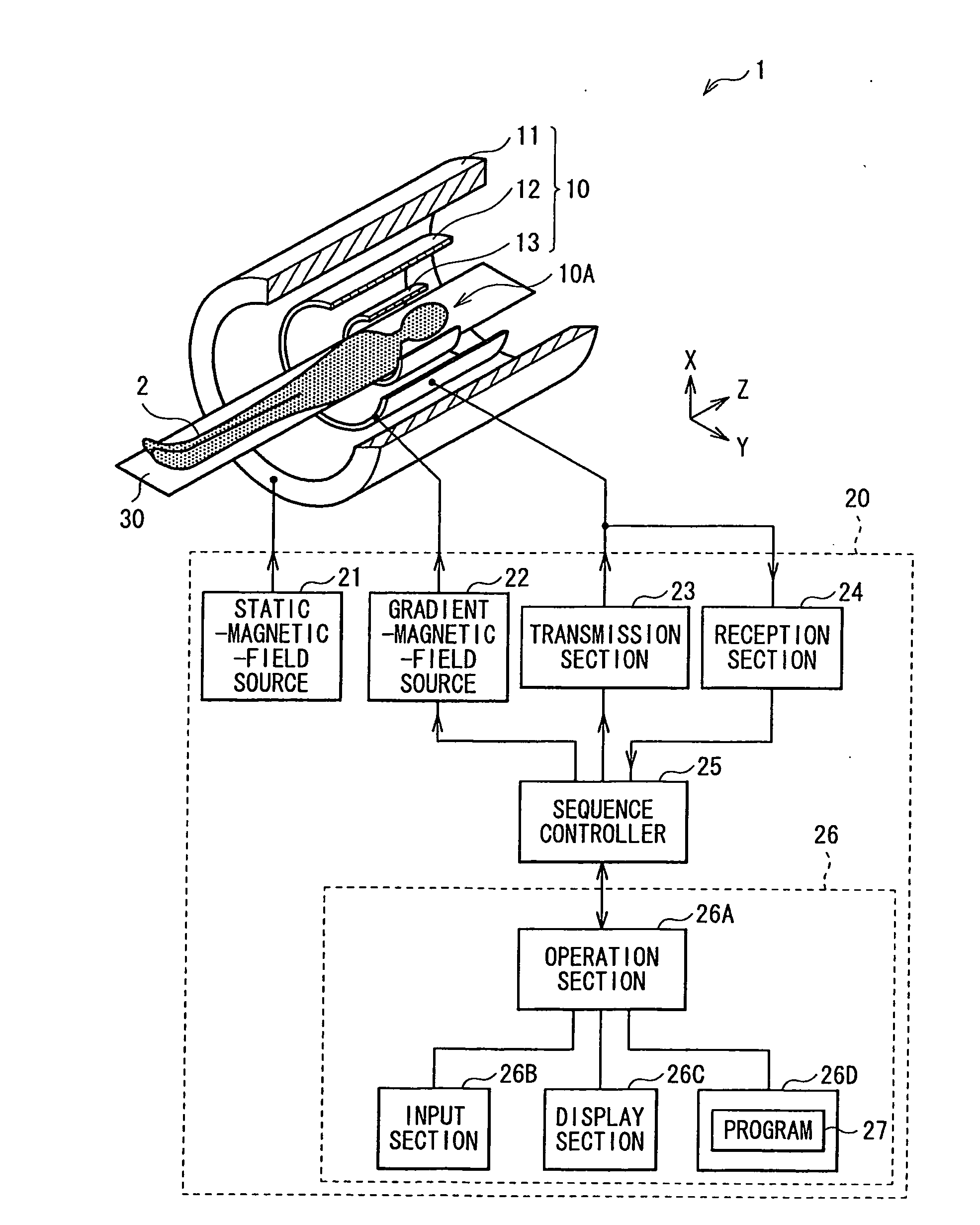
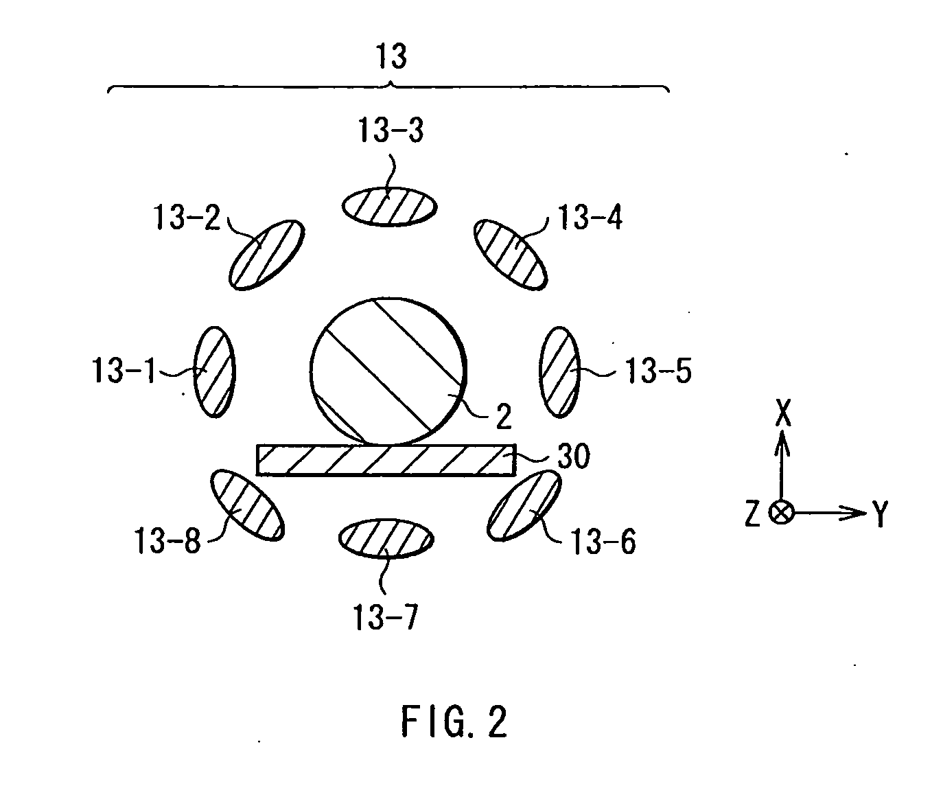
[0115]In the embodiment, when the RF coil section 13 includes, for example, a plurality of coils 13-1 to 13-8 (multiple channels) disposed on circumference about a central axis (not shown) of the subject 2 as shown in FIG. 2, while a single enhancement function w(θ) may be set, an enhancement function w(θ) is preferably set for each of channels in some cases.

[0116]For example, when the enhancement function w(θ) is set for each of channels, for example, the operation section 26A creates a morphological image Iindiv(x) in the following way. First, the operation section 26A acquires data (raw data Ri) (1≦i≦N: N is total number of channels) from a plurality of channels disposed in parallel around the subject 2, the data being corresponding to an MR signal detected for each of the channels. Next, the operation section 26A creates a magnitude image Mi(x), a phase image Pi(x), and a complex image ρi(x) for each of the channels based on the raw data Ri, and t...

second embodiment

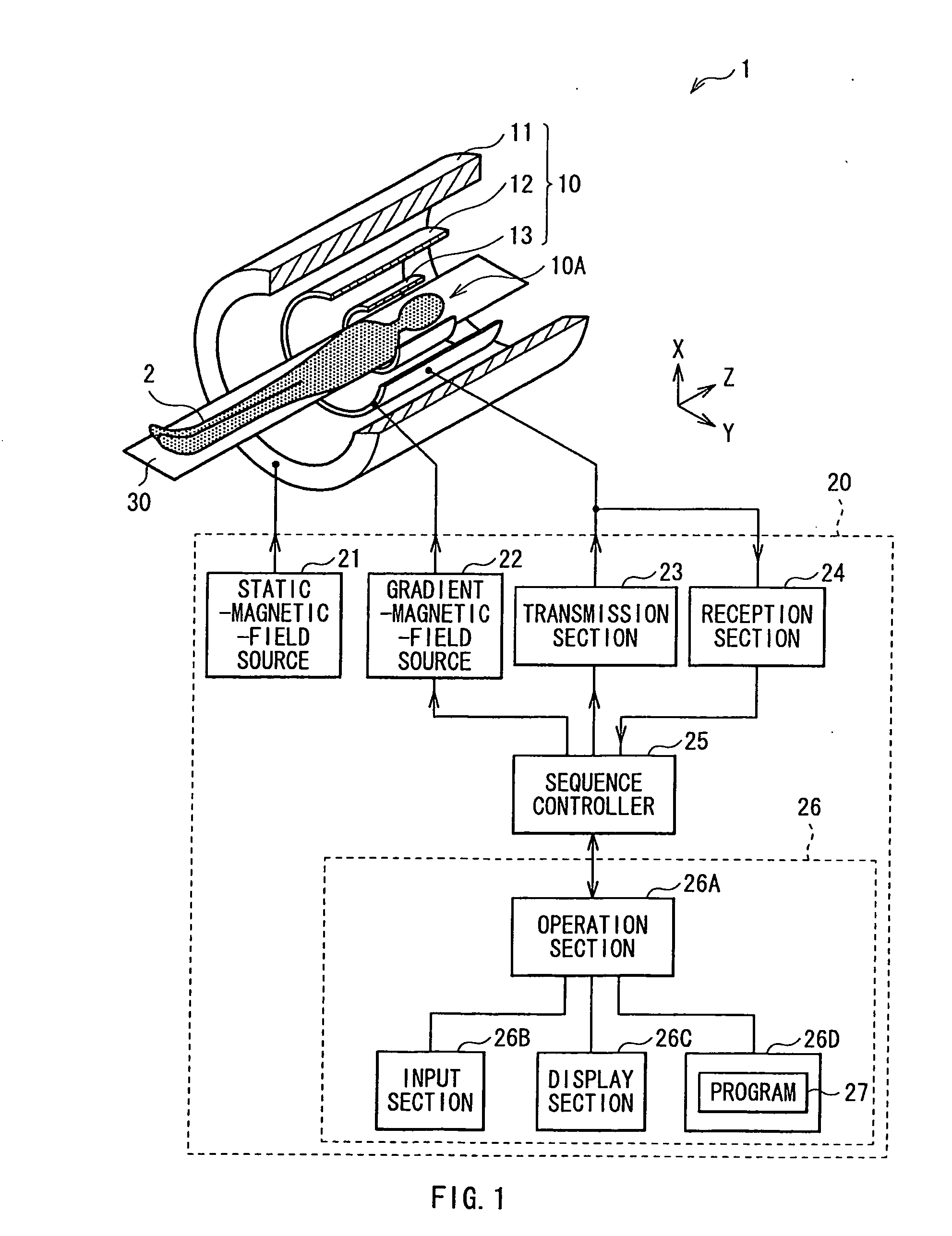
[0126]Next, an MRI apparatus according to a second embodiment of the invention is described. The MRI apparatus of the embodiment performs imaging of internal information of a subject 2 using an NMR phenomenon in the same way as the MRI apparatus 1 of the first embodiment. However, the MRI apparatus of the embodiment is different in configuration from the MRI apparatus 1 of the above embodiment in that the MRI apparatus has a function of fMRI, or a function of rendering an activated region. Thus, hereinafter, features different from the above embodiment are largely described, and description of features in common with the above embodiment is appropriately omitted.

[0127]In the embodiment, a storage section 26D storages various programs for controlling the MRI apparatus of the embodiment, for example, a program (functional image creating program) used for creating a function image as part of a program 27. Hereinafter, the function image is created through execution of a command in the ...


PUM


Abstract

A functional image creating method and a functional image creating apparatus, each enabling rendering of an activated region, are provided. A phase difference image PDr(x) is created using a complex image σr(x) created from an MR signal in an inactive state and a complex image σ′r(x) obtained by filtering the complex image σr(x). A phase difference image PDa(x) is created using a complex image σa(x) created from an MR signal in an active state and a complex image σ′a(x) obtained by filtering the complex image σa(x). Function signal images diff1(x) and diff2(x) are created using the phase difference images PDr(x) and PDa(x), respectively. A magnitude image Mr(x), a magnitude image Ma(x), a standard image, or a morphological image I(x) is masked with the function signal image diff1(x) or diff2(x), thereby a function image I′(x) with an activated region rendered is created.

Description

TECHNICAL FIELD[0001]The present invention relates to, for enhancement of an objective tissue, a phase difference enhanced imaging method, a phase difference enhanced imaging program, a phase difference enhanced imaging apparatus, and a magnetic resonance imaging apparatus. In addition, the invention relates to a functional image creating method and a functional image creating apparatus for rendering an activated region.BACKGROUND ART[0002]MRI is a method of imaging internal information of a subject body using a NMR (Nuclear Magnetic Resonance) phenomenon. A complex image having a size and an angle of a rotating magnetization vector is obtained as an MR image. In the past, a magnitude image, obtained by imaging only magnitude of an MR signal, has been used as the MR image. However, since unevenness of a magnetic field has been adequately reduced due to recent progress of MRI technology, a phase image obtained by imaging a rotational angle of a magnetization vector is now available. ...

Claims


Application Information

Patent Timeline
Patent Type & Authority Applications(United States)
IPC IPC(8): G01R33/48G06K9/00
CPCG01R33/4806G01R33/5608G01R33/56G01R33/56536A61B5/055A61B5/4064A61B5/0042
Inventor YONEDA, TETSUYAHIAI, YASUHIRO
Owner NATIONAL UNIVERSITY
Learn More