Flaring methodologies for marine seismic data acquisition

a technology of seismic data and flaring methods, applied in seismology, seismic data for water-covered areas, instruments, etc., can solve the problems of affecting the quality and utility of the resulting seismic data, unable to acquire any large survey arrangement, and gaps left without coverage, so as to avoid unnecessary infill passes

Inactive Publication Date: 2011-12-15
CONOCOPHILLIPS CO
View PDF3 Cites 15 Cited by
  • Summary
  • Abstract
  • Description
  • Claims
  • Application Information

AI Technical Summary

Benefits of technology

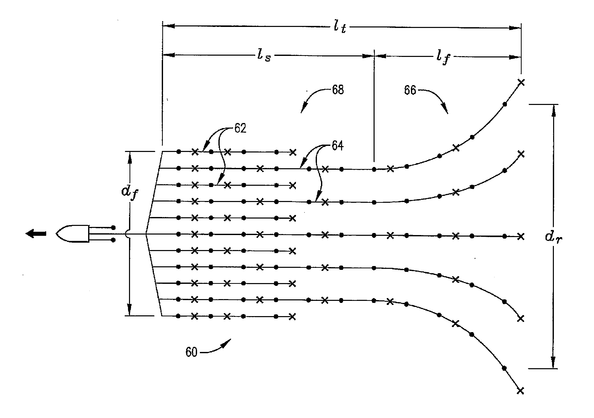
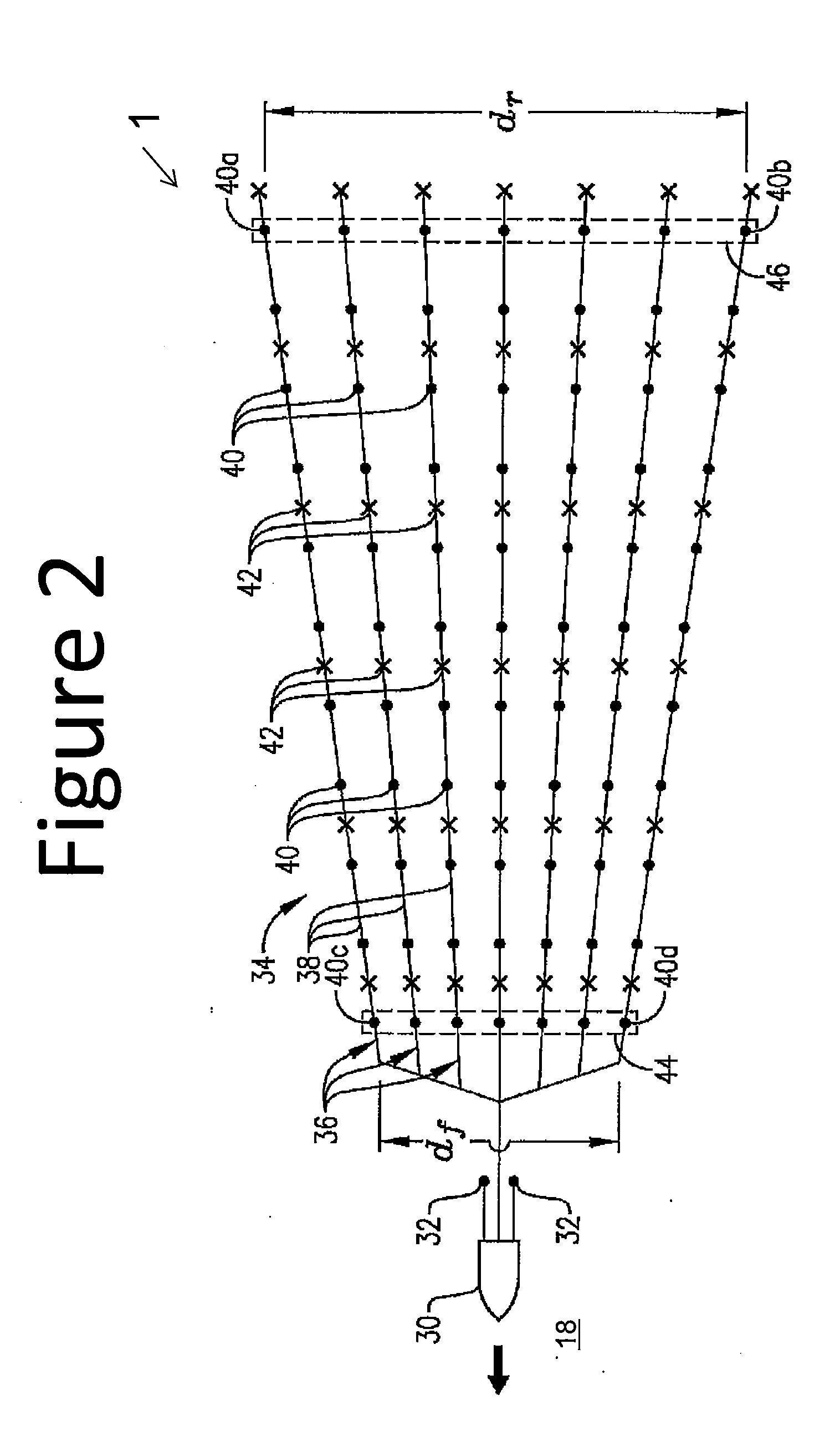
[0010]This invention relates to a method for determining the optimal flare spacing for streamers towed behind a seismic vessel. In particular, the method is based upon geophysical migration broadcast patterns to estimate a maximum sampling distance, and available interpolation algorithms to in-fill any gaps in data coverage. Specifically, the method comprises reprocessing prior seismic data from a survey area, and calculating an in-fill capability for different interpolation algorithms

Problems solved by technology

It is known that the relative positions of the marine seismic receivers during seismic data acquisition can affect the quality and utility of the resulting seismic data.
Unfortunately tides, winds and currents conspire to make this arrangement nearly impossible to acquire for any large survey.
These gaps are left with no coverage due to sea states pushing the streamers out of position.
Currently technology limits of the interpolation algorithms limit the number of missed bins or gaps that can be interpolated to about 4 bins.
A common problem encountered with conventional marine seismic surveys is “gaps” in the acquired seismic data.
These data gaps are basically holes in coverage that have no data.
They can occur when the spacing between adjacent acquisition passes is too large to provide sufficient resolution for proper data processing.
Even when steerable streamers are employed, gaps in seismic data are common, particularly when strong crosscurrents are present or when acquiring data with a trailing current o

Method used


Image

  • Flaring methodologies for marine seismic data acquisition
  • Flaring methodologies for marine seismic data acquisition
  • Flaring methodologies for marine seismic data acquisition

Examples


Embodiment Construction

[0018]Turning now to the detailed description of the preferred arrangement or arrangements of the present invention, it should be understood that the inventive features and concepts may be manifested in other arrangements and that the scope of the invention is not limited to the embodiments described or illustrated. The scope of the invention is intended only to be limited by the scope of the claims that follow.

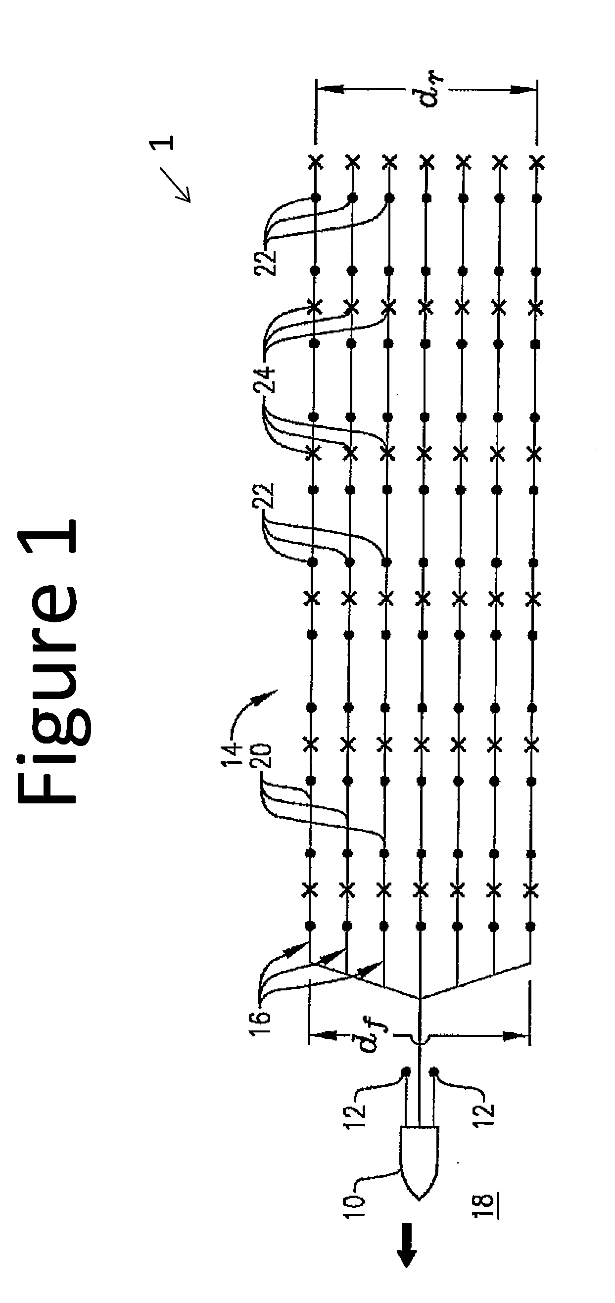
[0019]An exemplary marine seismic data acquisition system 1, where the streamer spacing is substantially constant over the entire length of the streamers, is shown in FIG. 1. As shown in FIG. 1, the data acquisition system 1 employs a marine vessel 10 to tow seismic sources 12 and a system 14 of steerable seismic streamers 16 through a body of water 18. Each of the seismic streamers 16 includes a streamer cable 20, a series of seismic receivers 22 coupled to the cable 20, and a series of steering devices 24 coupled to the cable 20. During marine seismic data acquisition, the ...


PUM


Abstract

A method of determining an optimal flare spacing for streamers towed behind a seismic vessel comprising the steps of: using a computer specially adapted with a seismic data analysis package to analyze prior seismic data for a survey area; analyzing migration broadcast patterns to estimate a maximum sampling distance; calculating a wavelet expansion as a function of flare spacing; creating synthetic gaps in the prior seismic data coverage by dropping traces at different flare spacing; testing capability of different interpolation algorithms in the seismic data analysis package to close the synthetic gaps; and determining an optimal flare spacing based upon the capability of the different interpolation algorithms to close the synthetic gaps.

Description

CROSS-REFERENCE TO RELATED APPLICATIONS[0001]This application is a non-provisional application which claims benefit under 35 USC §119(e) to U.S. Provisional Application Ser. No. 61 / 352,098 filed Jun. 7, 2010, entitled “Flaring Methodologies For Marine Seismic Data Acquisition,” which is incorporated herein in its entirety.STATEMENT REGARDING FEDERALLY SPONSORED RESEARCH OR DEVELOPMENT[0002]None.FIELD OF THE INVENTION[0003]This invention relates generally to seismic data acquisition in marine environments using towed streamers behind a tow vessel.BACKGROUND OF THE INVENTION[0004]Marine seismic exploration investigates and maps the structure and character of subsurface geological formations underlying a body of water. Marine seismic data is typically gathered by towing seismic sources (e.g., air guns) and seismic receivers (e.g., hydrophones) through a body of water behind one or more marine vessels. As the seismic sources and receivers are towed through the water, the seismic sources...

Claims


Application Information

Patent Timeline
IPC IPC(8): G01V1/38
CPCG01V1/3826G01V1/3808
Inventor EICK, PETER M.BREWER, JOEL D.
Owner CONOCOPHILLIPS CO
Why Eureka
Try Eureka