Transmission apparatus, transmission method, communication system, and communication method

Active Publication Date: 2011-12-15
SHARP KK
View PDF15 Cites 42 Cited by
  • Summary
  • Abstract
  • Description
  • Claims
  • Application Information

AI Technical Summary

Benefits of technology

[0016]According to the present invention, it is possible to improve the resistance to ISI without substantially degrading transmission efficiency because a first OFDM symbol and a second OFDM symbol can be generated, first and second GIs having different lengths can be added to the first and second OFDM symbols (wh

Problems solved by technology

In wireless communication such as mobile communication or fixed communication, a transmission signal is subjected to various interferences by the influence of reflection waves due to obstacles in a propagation channel, and th

Method used


Image

  • Transmission apparatus, transmission method, communication system, and communication method
  • Transmission apparatus, transmission method, communication system, and communication method
  • Transmission apparatus, transmission method, communication system, and communication method

Examples


Example

First Embodiment

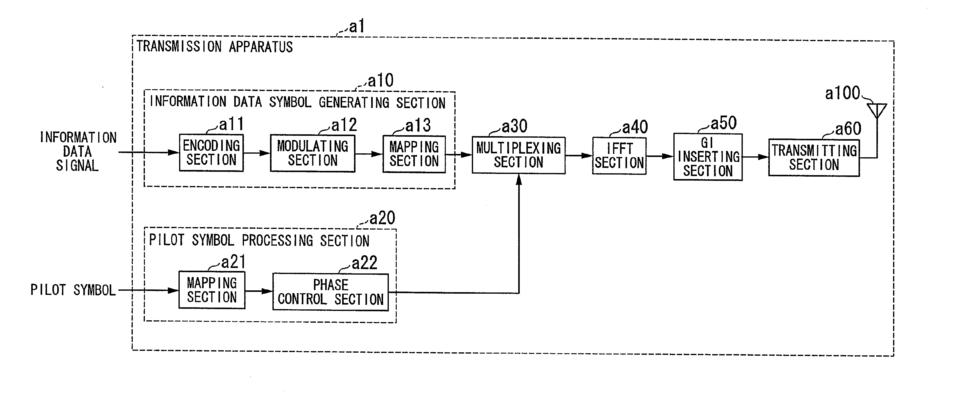
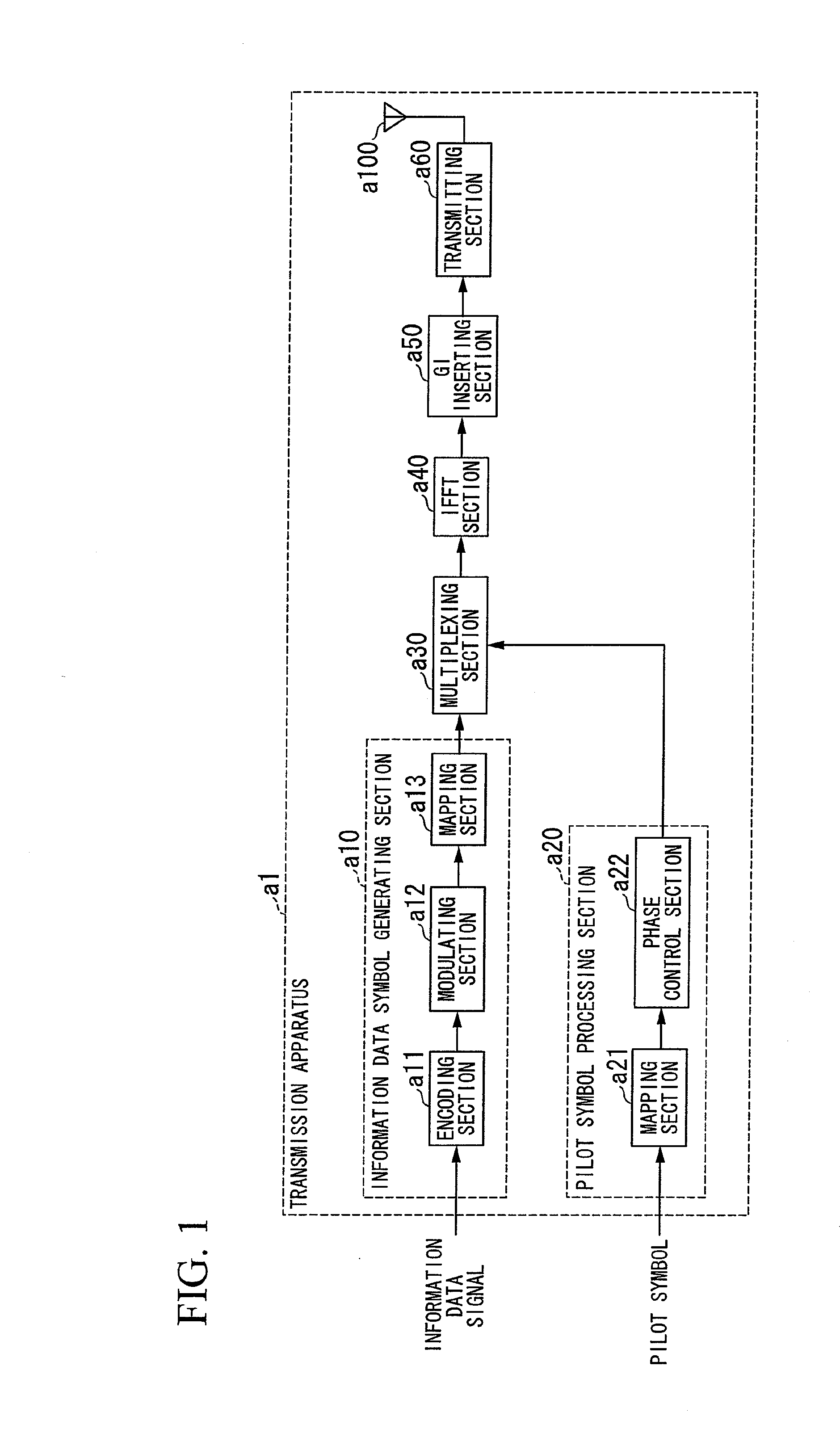
[0084]Hereinafter, the first embodiment of the present invention will be described. A communication system according to the first embodiment includes a transmission apparatus and a reception apparatus. FIG. 1 is a schematic block diagram showing a configuration of the transmission apparatus according to the first embodiment of the present invention. In FIG. 1, a transmission apparatus a1 includes an information data symbol generating section a10 (a normal GI symbol generating section), a pilot symbol processing section a20 (a long GI symbol generating section), a multiplexing section a30, an IFFT (inverse fast Fourier transform) section a40, a GI inserting section a50, a transmitting section a60 (a radio transmitting section), and a transmission antenna a100.

[0085]The information data symbol generating section a10 arranges (maps) an information data symbol obtained by encoding and modulating an information data signal (transmission data) to be transmitted, which is i...

Example

Second Embodiment

[0161]Next, the case where a generated pilot symbol is stored as the second embodiment of the present invention will be described. A communication system according to the second embodiment includes a transmission apparatus and a reception apparatus. FIG. 16 is a schematic block diagram showing a configuration of the transmission apparatus according to the second embodiment. In FIG. 16, a transmission apparatus a2 includes an information data symbol generating section a10, a pilot symbol processing section a20, a pilot symbol storage section a70 (a symbol storage section), a multiplexing section a32, an IFFT section a40, a GI inserting section a50, a transmitting section a60, and a transmission antenna a100.

[0162]In the configuration of the transmission apparatus a2 of FIG. 16, a difference from the transmission apparatus a1 according to the first embodiment shown in FIG. 1 is that the pilot symbol storage section a70 is added after the pilot symbol processing sectio...

Example

Third Embodiment

[0173]Next, the case where control data is transmitted will be described as the third embodiment of the present invention. A communication system according to the third embodiment includes a transmission apparatus and a reception apparatus. FIG. 17 is a schematic block diagram showing a configuration of the transmission apparatus according to the third embodiment. In FIG. 17, a transmission apparatus a3 includes an information data symbol generating section a10, a control symbol processing section a80, a multiplexing section a33, an IFFT section a40, a GI inserting section a50, a transmitting section a60, and a transmission antenna a100.

[0174]In the configuration of the transmission apparatus a3 of FIG. 17, a difference from the transmitter a1 according to the first embodiment shown in FIG. 1 is that the pilot symbol processing section a20 is replaced by the control symbol processing section a80. Instead of the pilot symbol input to the transmission apparatus a1 in t...


PUM


Abstract

In a transmission apparatus which multicarrier-modulates and transmits symbols, which are basic units of digital signals, a subcarrier in which a symbol is arranged in a first multicarrier symbol having a first guard interval and a subcarrier in which a symbol is arranged in a second multicarrier symbol having a second guard interval longer than the first guard interval are scattered among a plurality of subcarriers constituting a multicarrier at the same time. Therefore, it is possible to improve the resistance to inter-symbol interference without substantially degrading transmission efficiency.

Description

TECHNICAL FIELD[0001]The present invention relates to a transmission apparatus, a transmission method, a communication system, and a communication method.[0002]This application claims priority to and the benefits of Japanese Patent Application Nos. 2009-002693 and 2009-002694 filed on Jan. 8, 2009, the disclosure of which is incorporated herein by reference.BACKGROUND ART[0003]In wireless communication such as mobile communication or fixed communication, a transmission signal is subjected to various interferences by the influence of reflection waves due to obstacles in a propagation channel, and the like and communication quality is degraded by fading in which a level of a reception signal is changed.[0004]For example, the influence of multipath fading (multipath interference) is reduced by adding a guard interval (GI) (length) based on a cyclic prefix (CP) to a transmission signal transmitted by a transmission apparatus in multicarrier transmission such as orthogonal frequency divi...

Claims


Application Information

Patent Timeline
IPC IPC(8): H04L27/00H04L27/28
CPCH04L27/2607H04L27/2688H04L27/2646
Inventor SHIMEZAWA, KAZUYUKINOGAMI, TOSHIZOYOSHIMOTO, TAKASHIYAMADA, RYOTAKATO, KATSUYA
Owner SHARP KK
Why Eureka
Try Eureka