Side sliding door apparatus for vehicle

a technology for sliding doors and vehicles, applied in the direction of locking applications, wing accessories, transportation and packaging, etc., to achieve the effect of convenient operation, simple position setting of switches, and reliable results

Active Publication Date: 2011-12-22
FUJI ELECTRIC CO LTD
View PDF13 Cites 20 Cited by
  • Summary
  • Abstract
  • Description
  • Claims
  • Application Information

AI Technical Summary

Benefits of technology

[0030]The reliability is further increased by the configurations of the above first and second aspects used together.
[0031]3. Meanwhile, according to the third aspect, which provides a mechanical limit switch instead of the heretofore known magnetic proximity switch in order to simplify the position setting of the switch that detects the unlocking or locking of the sliding doors from the up and down movement of the latch, the limit switch has no hysteresis, so that the operational position when locking and unlocking is constant, the position adjustment when attaching is simpler, and operating accuracy increases.
[0032]As heretofore described, according to the invention, it is possible to prevent malfunction whereby the locking of the sliding doors becomes impossible due to an external force such as vibration. In addition, the locking detection function becomes more dependable, which increases the operational reliability of the side sliding door apparatus for vehicle.

Problems solved by technology

However, it must be easily unlock the apparatus by a manual operation when an emergency situation such as a power cut occurs, the vehicle stops, and the passengers escape from the vehicle.

Method used


Image

  • Side sliding door apparatus for vehicle
  • Side sliding door apparatus for vehicle
  • Side sliding door apparatus for vehicle

Examples


Embodiment Construction

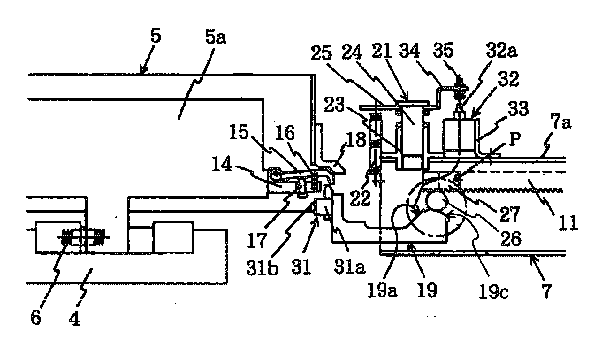
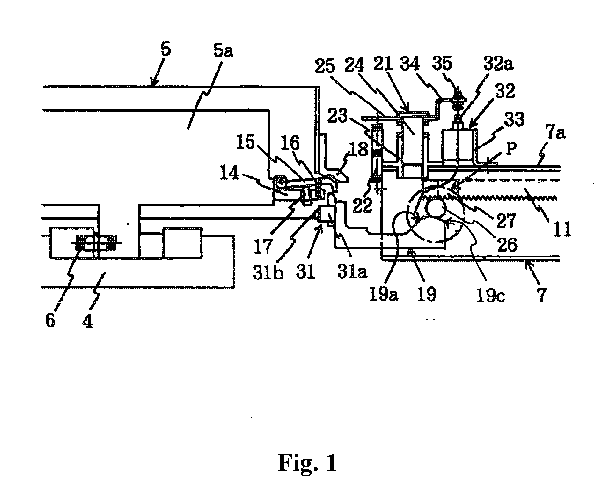
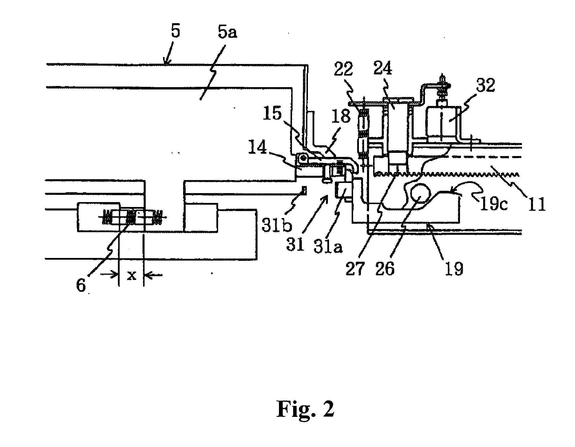
[0040]Hereafter, a description of an embodiment of the invention will be explained, based on the working example shown in FIGS. 1 to 3. The same reference numerals are used for portions corresponding to those in the heretofore known structure shown in FIGS. 4 to 7.

[0041]In FIGS. 1 to 3, a first difference from the conventional structure is that an upper level surface 19c of a cam surface 19a of a slider 19 is formed in such a way as to be an inclined surface inclined in a downward gradient from a starting end (left side) to a finishing end (right end) of the upper level surface 19c (θ in the drawings represents an angle of inclination with the horizontal as a reference) and, in the unlocked position of FIG. 1, a roller 26 is held in a condition in which it is partway along the upper level surface 19c having the downward gradient. Herein, by testing and the like, the angle of inclination θ is fixed at an angle in a range of few to around 15 degrees, wherein there is a good balance be...


PUM


Abstract

A side sliding door apparatus for a vehicle includes one of two sliding doors driven by an actuator, and the other moves in conjunction with the one sliding door via a direction converting mechanism. When the sliding door is in a closed condition, a latch rod is inserted into a lock hole to lock the sliding doors in the closed condition. A roller is pushed up on a cam surface when the sliding doors are opened, which releases the locking. An upper level surface of the cam surface forms an inclined surface with a downward gradient, which prevents the roller from unexpectedly going beyond the starting end of the upper level surface and dropping due to vibration or the like being applied to the slider in the unlocked condition, and prevents the locking with the locking mechanism in response to the next sliding door closing command.

Description

BACKGROUND OF THE INVENTION AND RELATED ART STATEMENT[0001]The present invention relates to a side sliding door apparatus that opens and closes a side entrance of a vehicle such as an electric railcar.[0002]As the side sliding door apparatus is entrusted with the lives of the passengers, it must not open arbitrarily from a condition in which the doors are closed, regardless of whether the vehicle is in motion or stationary, and it must consistently be maintained in a closed position by a constant pressure in order to prevent the ingress of rain water or wind, to prevent vibration while in motion, and the like. However, it must be easily unlock the apparatus by a manual operation when an emergency situation such as a power cut occurs, the vehicle stops, and the passengers escape from the vehicle. Because of the above points, a high operational reliability is required for the side sliding door apparatus for vehicle. The present inventor has developed a side sliding door apparatus for ...

Claims


Application Information

Patent Timeline
Patent Type & Authority Applications(United States)
IPC IPC(8): E06B3/46E05B65/08E05F11/54E05F15/60B61D19/00B61D19/02E05C7/06
CPCB61D19/026E05B81/00E05B83/02E05Y2201/218E05Y2201/412E05F15/655E05Y2800/25E05Y2800/422E05Y2900/51E05F15/40E05F15/60E05Y2201/46
Inventor TERASAKI, TOMIOKITABATA, ATSUSHI
Owner FUJI ELECTRIC CO LTD
Why Eureka
Try Eureka