Pump Cavitation Device

a cavitation device and pump technology, applied in the field of pumps, can solve the problems of early failure of components, leakage in sealing areas, loss of pressure integrity, etc., and achieve the effect of reducing the cavitation extending the working life of the component, and reducing the damage of a component having a sacrificial member

Inactive Publication Date: 2011-12-22
S P M FLOW CONTROL
View PDF9 Cites 22 Cited by
  • Summary
  • Abstract
  • Description
  • Claims
  • Application Information

AI Technical Summary

Benefits of technology

[0007]In a first aspect, embodiments are disclosed of a method that reduces cavitation damage to a component within a pump including mounting a sacrificial body within the pump and operating the pump to pump fluid at a rate that causes at least some cavitation to occur on the component, wherein the pumped fluid flows over the sacrificial body to shed

Problems solved by technology

Cavitation in pumping devices causes early failure of components due to erosion/corrosion and the resulting pitting.
The pitting causes several problems: leaks in sealing areas, loss of pressure integrity, or loss of pressure integrity due to sudden catastrophic failure from a crack in the pressure chamber that begins at a cavitation corrosion pit and rapidly propagates through the pressure containing wall of the pumping chamber.
Small air bubbles are formed and the collapsing of the bubbles can reach boundary velocities high enough to erode the metal away, causing pitting.
These hydrogen ions have a corrosive effect on the molecular structure of the metal, causing small particles of the metal to separate and enter into the fluid stream, contributing to further acceleration of the pitting process.
These hydrogen ions cause the formation of hydrogen embrittlement cracks, which propogate during each pumping stroke of a reciprocating pump.
Eventually this cracking begins to penetrate into the pressure containing wall and rapidly results in a structural failure of the pressure vessel.
In applications where a lot of fluid is pumped at high velocities, the maintenance costs due to cavitation erosion/corrosion can be a significant p

Method used


Image

  • Pump Cavitation Device
  • Pump Cavitation Device
  • Pump Cavitation Device

Examples


Embodiment Construction

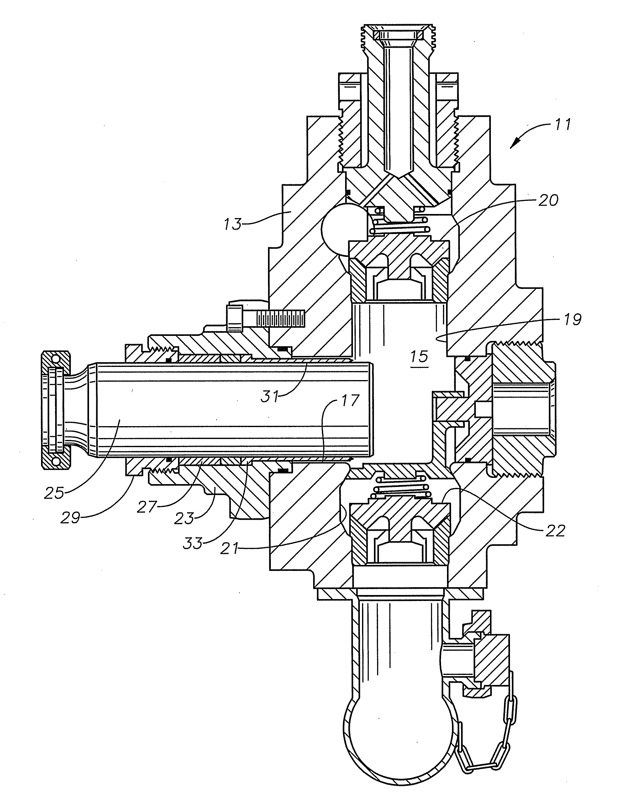
[0060]Referring to FIG. 1, a fluid end 11 illustrates one portion of a reciprocating pump of a type that is typically used in the well frac industry. The fluid end 11 is part of a surface mounted pump, typically mounted on a truck. The fluid end 11 is not submersed in the fluid to be pumped; rather a flowline leads to the fluid 11 to convey it to be pumped. The fluid end 11 includes a fluid end block 13 having a chamber 15. A plunger bore 17 intersects the chamber 15 on one side. A discharge valve port or passage 19 leads from the chamber 15; a suction on inlet port or passage 21 leads from the chamber 15 in a generally opposite direction. In this embodiment, the discharge and suction passages 19 and 21 are coaxial and perpendicular to the plunger bore 17, but they could be at different angles relative to each other and to the plunger bore 17.

[0061]A schematically shown discharge valve 20 is located in the discharge passage 19. The discharge valve 20 is spring-biased to a closed pos...


PUM


Abstract

A sacrificial body mitigates cavitation damage to components within a pump. The sacrificial body is mounted in the pump so that flowing fluid passes over the sacrificial body, which causes the sacrificial body to shed electrons into the flowing fluid in the vicinity of the cavitation. The excess electrons tend to suppress hydrogen ions from releasing, which can mitigate cavitation. The sacrificial body is formed of a material having less resistance to corrosion due to the flowing fluid than the components of the pump. Needles are attached to the sacrificial body for immersion in the flowing fluid to facilitate the release of the electrons for the sacrificial body.

Description

CROSS-REFERENCE TO RELATED APPLICATION[0001]This application claims priority to provisional patent application Ser. No. 61 / 355,878, filed Jun. 17, 2010.TECHNICAL FIELD[0002]This disclosure relates in general to pumps and in particular to a sacrificial body that mitigates pitting and corrosion due to cavitation.BACKGROUND OF THE DISCLOSURE[0003]Cavitation in pumping devices causes early failure of components due to erosion / corrosion and the resulting pitting. The pitting causes several problems: leaks in sealing areas, loss of pressure integrity, or loss of pressure integrity due to sudden catastrophic failure from a crack in the pressure chamber that begins at a cavitation corrosion pit and rapidly propagates through the pressure containing wall of the pumping chamber. Cavitation usually initiates in predictable places such as, but not limited to, near the edge of a sealing surface, areas where there is a sudden drop in pressure that produces turbulent fluid flow, or at microscopic ...

Claims


Application Information

Patent Timeline
IPC IPC(8): C23F13/02F01D25/00
CPCC23F13/06C23F13/10C23F13/20F04B53/16F05C2201/903F05C2201/02F05C2201/021F05C2201/028F04B53/166
Inventor BYRNE, JOSEPH H.
Owner S P M FLOW CONTROL
Why Eureka
Try Eureka