Device and system for extracting tidal energy

a technology of moving fluid and device, applied in the direction of electric generator control, greenhouse gas reduction, renewable energy generation, etc., can solve the problems of large scale turbines that have to be operated, limited potential applications of such large scale turbines, and limitations of existing vertical axis turbines originating from savonius, darrieus or gorlov designs, etc., to achieve small fluctuations in amplitude

Inactive Publication Date: 2011-12-22
KEPPEL OFFSHORE & MARINE TECH CENT PTE LTD
View PDF5 Cites 22 Cited by
  • Summary
  • Abstract
  • Description
  • Claims
  • Application Information

AI Technical Summary

Benefits of technology

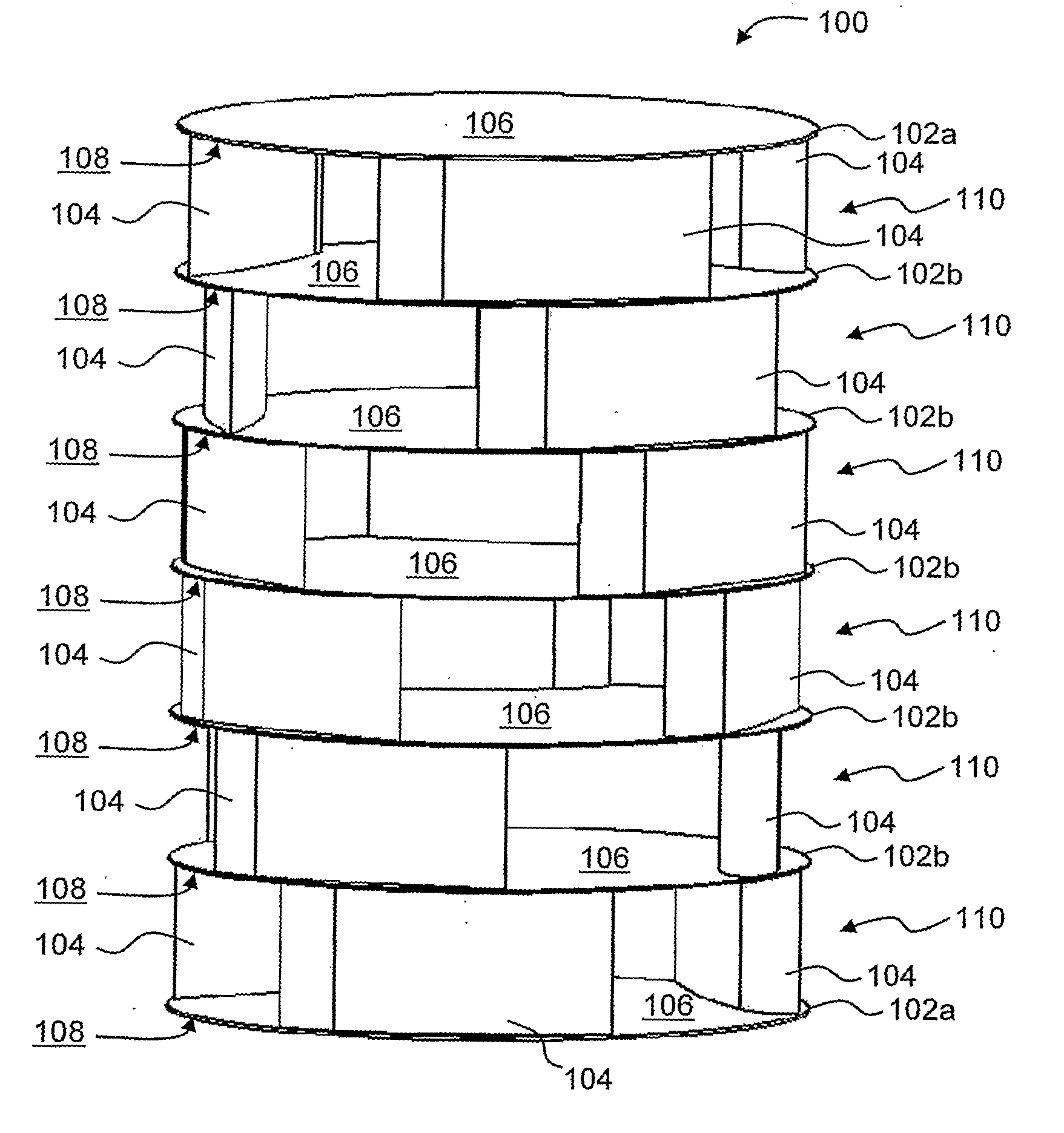
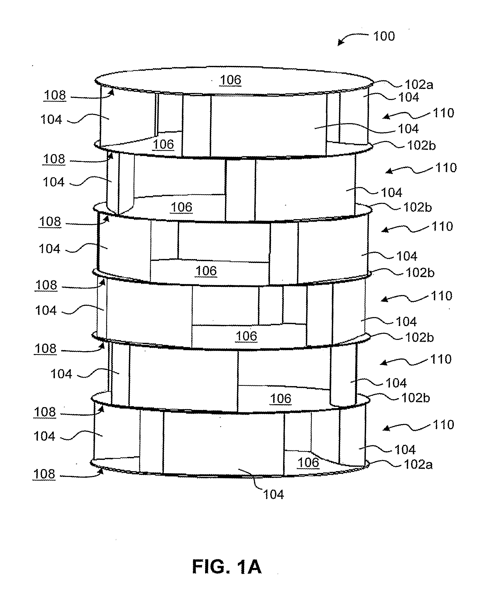
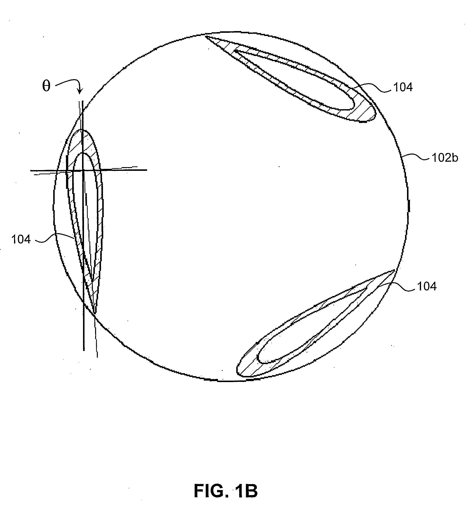
[0010]According to one embodiment of the invention, a turbine assembly may include identical sections disposed in a stacked arrangement. Outer plates may be disposed at opposed ends of the stacked arrangement. Each section includes a top surface, a bottom surface, and a plurality of airfoil-shaped blades fixedly mounted therebetween. A space within each section may be shaftless. The blades within each section may be arranged rotationally offset or displaced from blades within an adjacent section by a phase shift or an angle. With this rotational offset, each section is oriented at a phase shift to an adjacent section. When the sections are energized by a fluid flow to produce lift, the sections generate a plurality of progressively phase shifted torque outputs. Summation of the phase shifted torque outputs would result in a relatively constant resultant torque output with small fluctuations in amplitude.

Problems solved by technology

Consequently, these large scale turbines have to be operated in deep waters and at high tidal current flow speeds.
As such, the potential applications of such large scale turbines are severely limited.
Existing vertical axis turbines originating from Savonius, Darrieus or Gorlov designs have their limitations.
These torque fluctuations would result in undesirable fluctuations of electrical output.
However, Gorlov design is complex, costly to manufacture and has length limitation due to structural rigidity issues.
Such barrages are usually large-scale infrastructure, e.g. 750 meters in length, which requires high costs.
Construction of barrages also has a negative environment impact of silting and altering the local ecosystem.

Method used


Image

  • Device and system for extracting tidal energy
  • Device and system for extracting tidal energy
  • Device and system for extracting tidal energy

Examples


Embodiment Construction

[0035]In the following description, numerous specific details are set forth in order to provide a thorough understanding of various illustrative embodiments of the invention. It will be understood, however, to one skilled in the art, that embodiments of the invention may be practiced without some or all of these specific details. In other instances, well known process operations have not been described in detail in order not to unnecessarily obscure pertinent aspects of embodiments being described.

[0036]It will also be understood that, although the terms “first”, “second” and etc. may be used herein to describe various components, these components should not be limited by these terms. These terms are only used to distinguish one component from another, without departing from the scope of the invention. Further, it is to be understood that the use of the term “one another” in the present description is not restricted to a context of having three or more; the term also applies to a co...


PUM


Abstract

A turbine assembly and a system for extracting tidal energy are disclosed. The turbine assembly may include identical sections disposed in a stacked arrangement. Each section may be shaftless, energizable by a fluid flow to produce lift and is appropriately oriented at a phase shift to an adjacent section such that a relatively constant resultant torque output with small amplitude fluctuation is generated by rotation of the turbine assembly. The turbine assembly may be employed in conjunction with a velocity enhancing device having a housing with variable profile openings to enhance the torque output. The turbine assembly may further be employed in a floating barrage arrangement which is transportable.

Description

BACKGROUND[0001]1. Technical Field[0002]Embodiments of the invention relate generally to systems and methods of extracting energy from a moving fluid, e.g. tidal currents, and more particularly to turbines capable of generating a relatively constant resultant torque output and systems employing such turbines and velocity enhancing devices.[0003]2. Description of Related Art[0004]Tidal power, or tidal energy, is a form of kinetic energy inherent in water currents or tides. A device that converts this kinetic energy into a useful form is known as a tidal current device. Many existing tidal current devices employ horizontal axis turbines akin to wind turbines. These horizontal axis tidal current turbines are large scale devices with diameters typically more than 10 meters and are designed to generate electrical power in the megawatt range so as to reduce the total infrastructure costs per megawatt. Consequently, these large scale turbines have to be operated in deep waters and at high ...

Claims


Application Information

Patent Timeline
Patent Type & Authority Applications(United States)
IPC IPC(8): F03B13/10F04D27/00
CPCF03B3/18F03B13/264Y02E10/28Y02E10/223F05B2240/40Y02E10/20Y02E10/30
Inventor ETTANOOR THUPPALE, MOHAN DASSCHAN, CHARLIE CHUN TAWANG, SHENGYIN
Owner KEPPEL OFFSHORE & MARINE TECH CENT PTE LTD
Why Eureka
Try Eureka