
Centralized islanding protection for distributed renewable energy generators

Inactive Publication Date: 2011-12-22
PARKER INTANGIBLES LLC
View PDF5 Cites 45 Cited by
  • Summary
  • Abstract
  • Description
  • Claims
  • Application Information

AI Technical Summary

Benefits of technology

[0005]The invention is targeted for use in solar photovoltaic power plants which have a number of distributed DC-to-AC power converters. The invention eliminates the interaction of anti-islanding algorithms between multiple power converters, determines islanding conditions with a greater degree of certainty, reduces current distortion over prior art anti-islanding methods and provides a least-cost anti-islanding solution for systems with distributed power converters.

Problems solved by technology

Islanding or run-on is an abnormal operating condition where a grid-interactive power converter continues to supply power to grid-connected loads following the loss of the utility grid source.
The passive method alone will not detect an island under balanced conditions where available power out of the converter matches the power into grid-connected loads.
If however, the grid voltage source is lost, and therefore is not controlling the voltage at the PCC, then sufficient changes in power converter current can result in detectable changes in voltage or frequency across the grid-connected loads.
Prior art approaches to anti-islanding protection have a number of basic limitations.
(ii) Interaction—When multiple power converters are connected at the PCC, interactions between individual power converter anti-islanding algorithms may cause nuisance tripping or in the other extreme may cause an island to go undetected.

Method used


Image

  • Centralized islanding protection for distributed renewable energy generators
  • Centralized islanding protection for distributed renewable energy generators
  • Centralized islanding protection for distributed renewable energy generators

Examples


Embodiment Construction

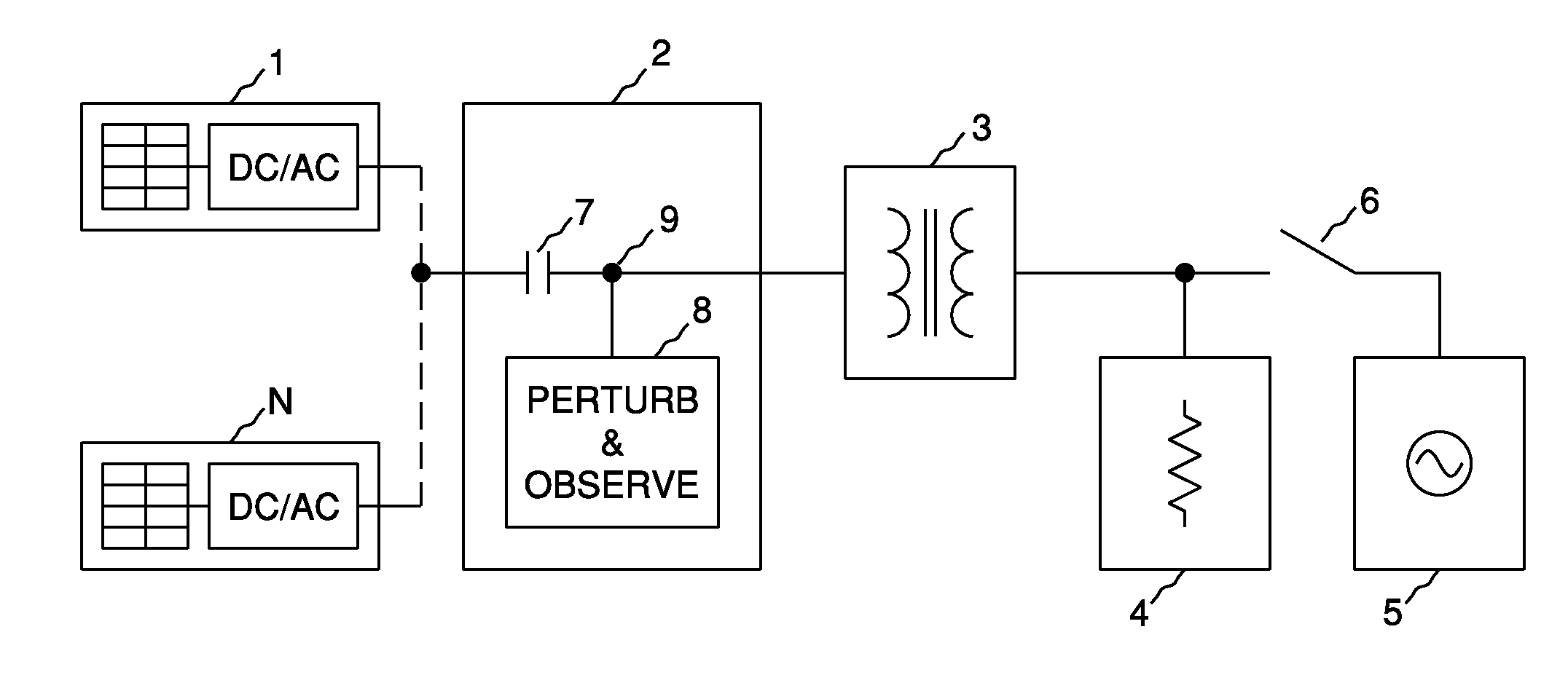
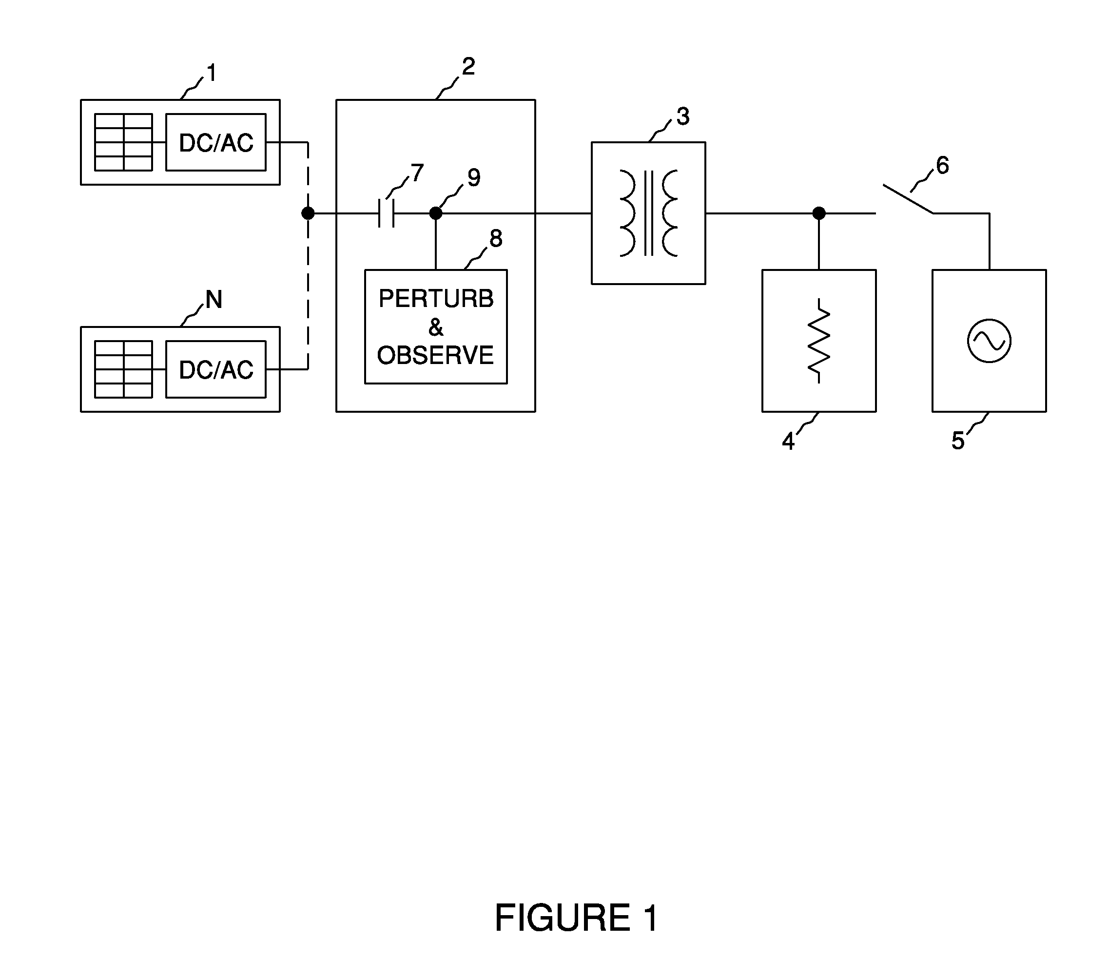
[0009]FIG. 1 shows how the invention is applied in a system. The system comprises a number of distributed photovoltaic power sources each with dedicated DC-to-AC power converters, 1 through N, protective anti-islanding device (the invention) 2, distribution transformer 3, grid-connected loads 4, AC grid source 5 and switch 6. The invention further comprises isolation contactor 7 and perturb and observe circuit block 8. Under normal operating conditions, isolation contactor 7 and switch 6 are closed and the net power transfer into grid source 5 is the combined output of DC to AC power converters, 1 through N, less the power consumed by grid-connected loads 4. An islanding fault condition is established when switch 6 is opened (functionally representing the loss grid source 5) and the power available from photovoltaic-to-AC power converters, 1 through N, matches the power consumed by grid-connected loads 4. An island or run-on condition may exist indefinitely as long as this source an...


PUM


Abstract

A device and method is disclosed for providing anti-islanding protection for an electrical grid-tied power converter, which is autonomous to the operation of the power converter. The device can protect any number of paralleled power converters and can independently determine if an islanding condition exists. The method involves actively perturbing the electrical grid at a common point of coupling between converter and grid, observing the effect of the perturbation, comparing the perturbed and non-perturbed grid characteristics and disconnecting the converter from the grid if a run-on or islanding condition is indicated. Perturbation is accomplished switching a reactive load or loads onto the grid or by changing a transformer tap connection at the point of common coupling.The invention is targeted for use in solar photovoltaic power plants which have a number of distributed DC-to-AC power converters. The invention eliminates the interaction of anti-islanding algorithms between multiple power converters, determines islanding conditions with a greater degree of certainty, reduces current distortion over prior art anti-islanding methods and provides a least-cost anti-islanding solution for systems with distributed power converters.

Description

BACKGROUND OF THE INVENTION[0001]All regulatory-code-compliant, utility-grid-interactive power converters must operate according to grid-connect standards for a given jurisdiction. In the United States, the governing standard is IEEE Standard for Interconnecting Distributed Resources with Electric Power Systems, commonly known as IEEE 1547. In short, this standard specifies that distributed resources, such a solar photovoltaic power converters, must provide a minimum power quality, must not operate outside of set utility voltage and frequency limits and must detect an islanding condition and automatically cease power production.[0002]Islanding or run-on is an abnormal operating condition where a grid-interactive power converter continues to supply power to grid-connected loads following the loss of the utility grid source. In simple terms, all grid-interactive power converters are current sources, whereas the grid source, typically the electric utility grid, is a voltage source. The...

Claims


Application Information

Patent Timeline
IPC IPC(8): H02J3/38
CPCH02J2003/388H02J3/383Y02E10/563H02J3/388H02J2300/24H02J3/381Y02E10/56
Inventor WEST, RICHARD TRAVIS
Owner PARKER INTANGIBLES LLC
Learn More