
Surface Structure for a Working Device

a surface structure and working device technology, applied in the direction of steering devices, cycle equipments, instruments, etc., can solve the problems of device providing a less secure and comfortable grip than the one provided by the device, the grip adhesion is not optimal, and the device is difficult to grasp

Active Publication Date: 2011-12-22
BRAUN GMBH
View PDF1 Cites 1 Cited by
  • Summary
  • Abstract
  • Description
  • Claims
  • Application Information

AI Technical Summary

Benefits of technology

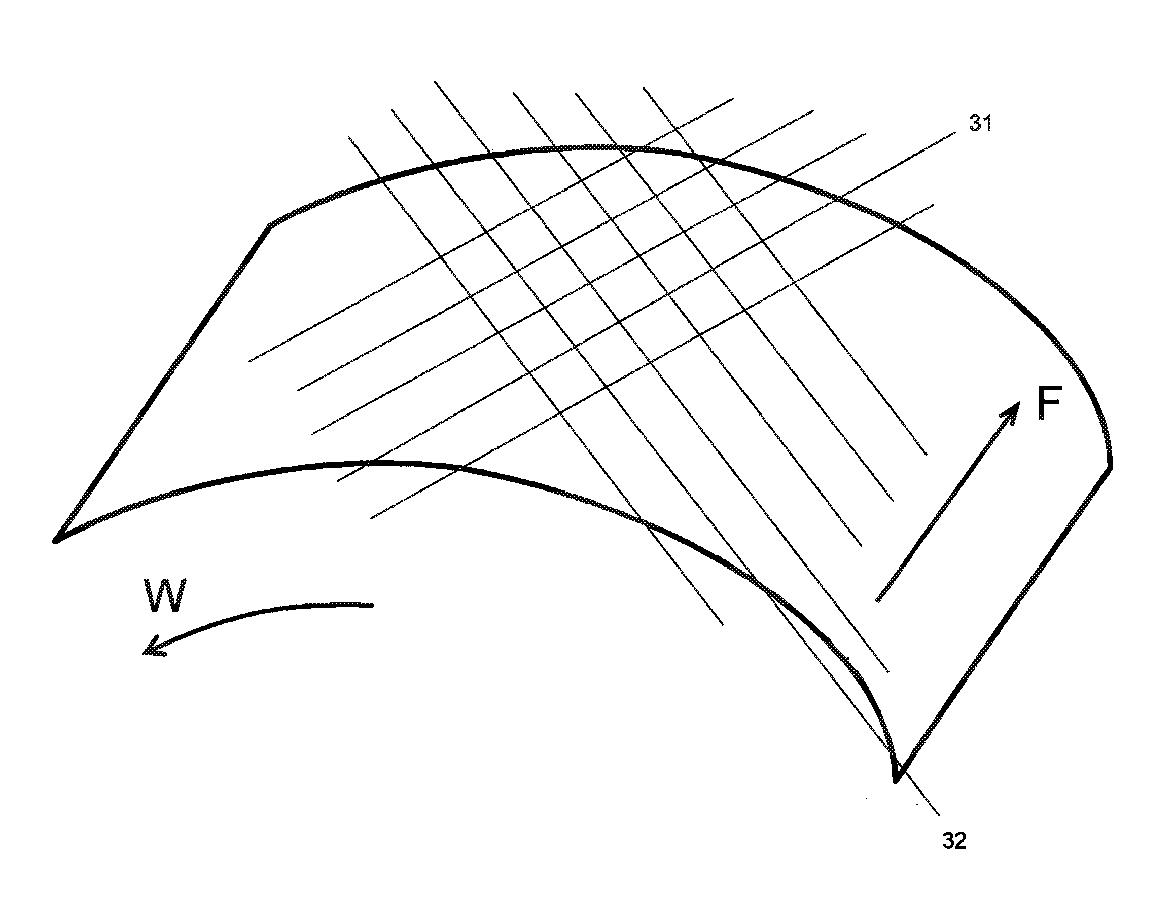
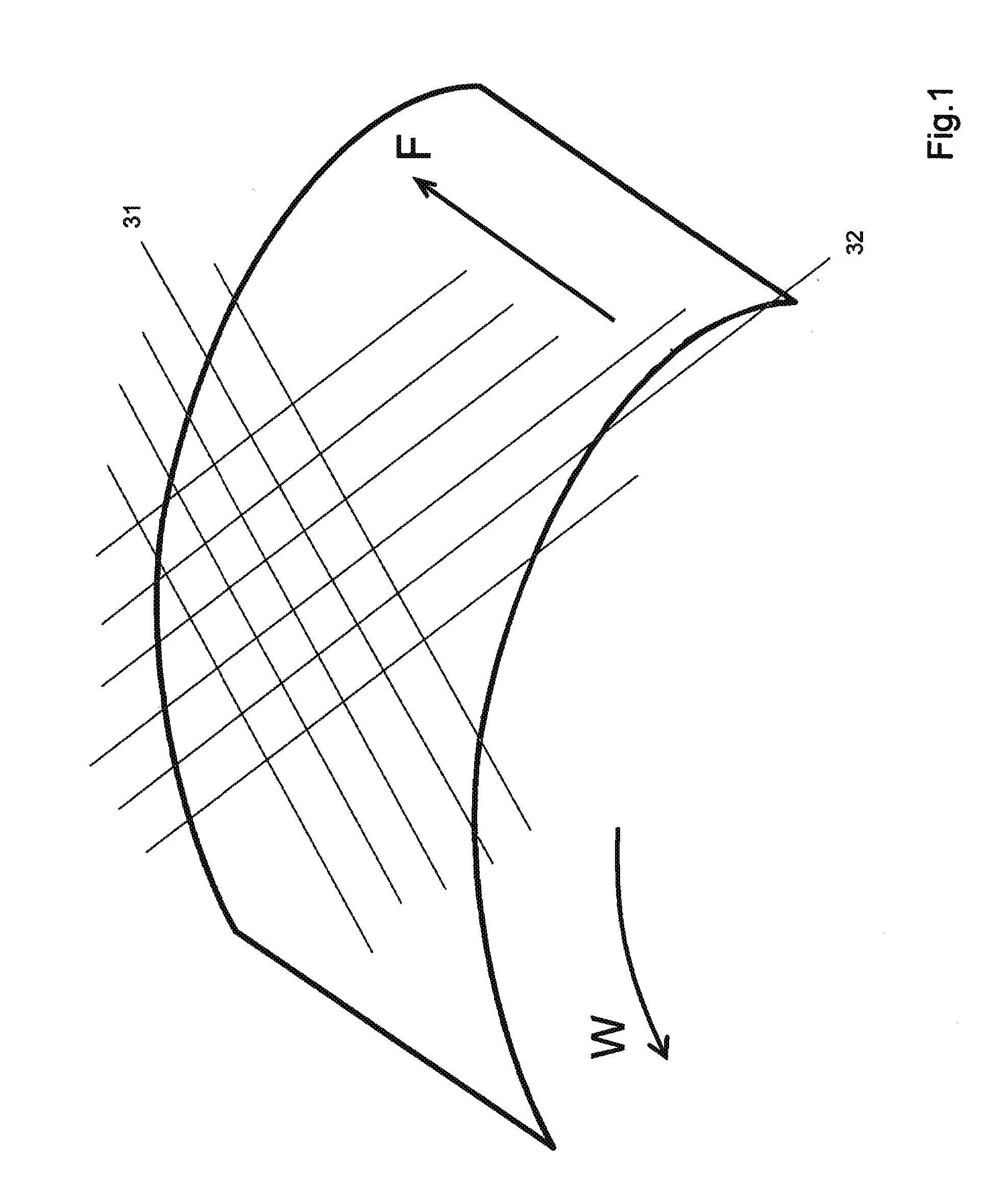
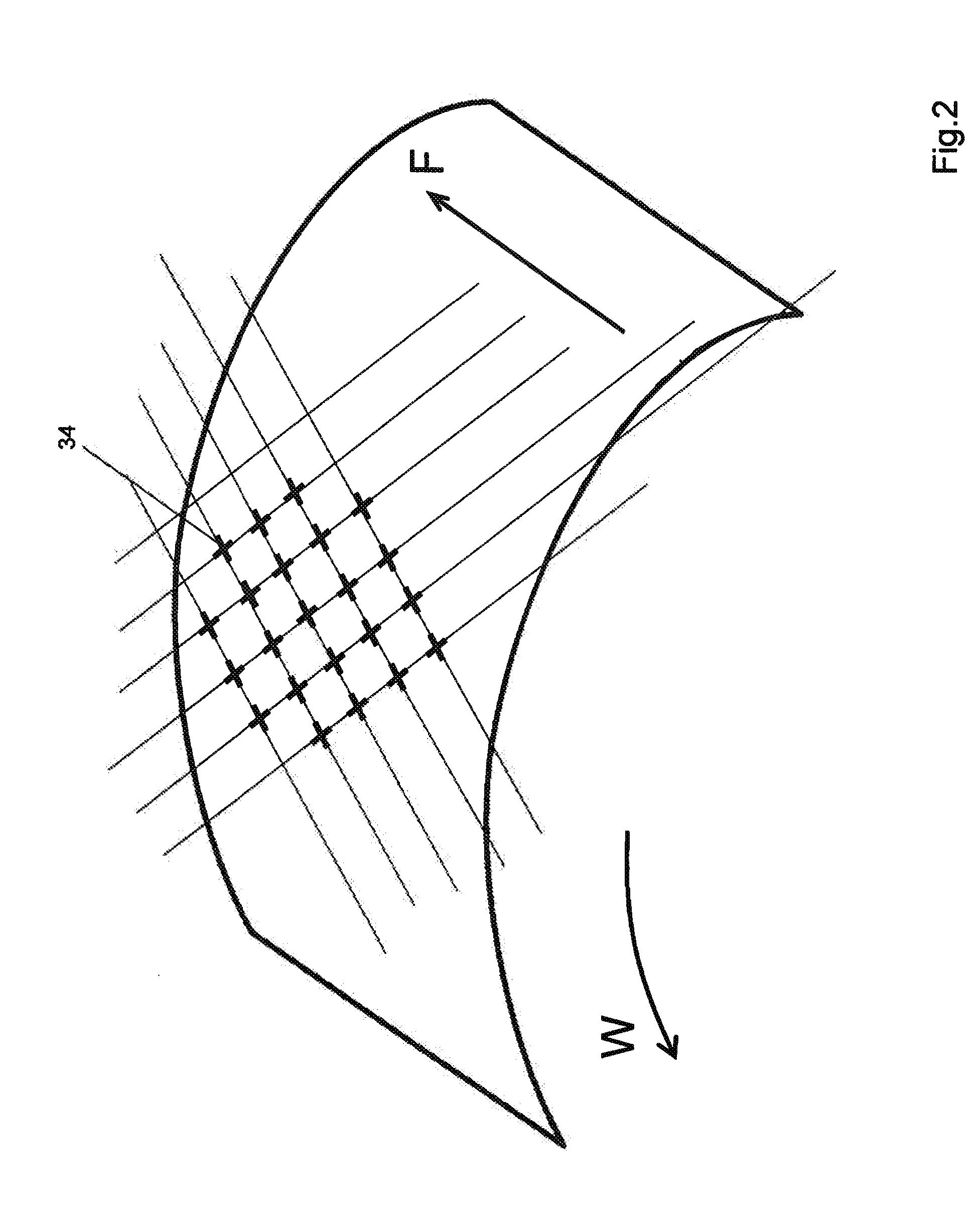
[0015]In a development of the invention according to Claim 2, the dot matrix is produced by parallel lines. This results in a dot matrix that is easy to define, promoting easy realization of the present invention, and also offering cost advantages with regard to machine-based implementation of the invention. Moreover, such a dot matrix can define grip areas in a particularly easily visible manner, thus promoting intuitive grasping in an ergonomically advantageous manner.
[0016]According to the development of the invention according to Claim 3, the second grip area contains three times as many second elements as first elements. In this way, the second grip area is set off particularly clearly from the first grip area. In particular because they produce stronger friction with the hand, the first elements in the first grip area can allow a particularly secure grip. However, here there is also an increased transmission of vibration. Therefore, it can be advantageous to keep the number of first elements in the second grip area low, or to provide no first elements at all in the second grip area.
[0020]The development of the invention according to Claim 7 provides that the height (h1) of the first elements is in turn greater than the height (h3) of the third elements. In other words, therefore, the height (h3) of the third elements is lower than the height (h1) of the first elements, and, according to the invention, is also lower than the height (h2) of the second elements. Therefore, these third elements act more as auxiliary elements helping to avoid excess slipperiness of the surface. Intuitively, however, the user of the surface structure will not grasp the handle in the area of the third elements if their height is particularly low.
[0023]According to a development of the invention according to Claim 10, it is also possible to use elements that, in a top view of the surface, are essentially semicircular in shape, or that are arranged symmetrically around a circular segment or a semicircle. Such elements have proven to be easy to grasp, and offer a high degree of grip security.

Problems solved by technology

However, when the handle is wet the grip adhesion is not optimal.
If the device is held differently, it is difficult to grasp.
In fact, when held differently this device provides an even less secure and comfortable grip than a smooth handle.
However, in an electrically operated device, grasping comfort is greatest when the vibrations that almost unavoidably occur due to the electrical operation of the device are transferred to the hand only to a limited extent.
The disclosed surface made of hard plastic, which is much larger than the surface of the knobs, will however probably result in a significant transmission of vibration.
In addition, this surface structure is intended to transmit vibrations of the working device only to a limited extent.

Method used


Image

  • Surface Structure for a Working Device
  • Surface Structure for a Working Device
  • Surface Structure for a Working Device

Examples


Embodiment Construction

[0007]A surface structure having these advantages is the surface structure claimed in Claim 1. The surface structures in the subclaims offer specific advantages.

[0008]Thus, the surface structure has at least three elements, namely a first element, a second element, and a third element. Such elements may have any shape, as long as they can be distinguished from the surface structure. The elements may be recesses in the surface structure, but as a rule are raised parts. The elements have a base surface. To the extent that the elements are formed integrally with the surface structure, the base surface results from extrapolation of the surface in the vicinity of the elements. The elements also have at least one side surface. For example, an element may have the shape of a segment of a sphere. The element then has, in addition to the base surface, only one limiting surface. This surface on the sphere surface is designated here as a side surface. However, the element can also be pyramid-s...


PUM

PropertyMeasurementUnit
angleaaaaaaaaaa
angleaaaaaaaaaa
angleaaaaaaaaaa

Abstract

The present invention relates to a surface structure for a working device. In particular, the invention relates to a surface structure for a working device that has at least one first element with a first height and a second element with a second height, and a third element having a third height, wherein the second height is greater than the third height, having in addition a first grip area, a second grip area, and a third grip area, wherein the elements are arranged on a dot matrix, wherein the centers of the second elements and the centers of the third elements are arranged on the points of intersection and the centers of the first elements are not arranged on the points of intersection, and the first grip area comprises first elements and second elements, the second grip area comprises predominantly second elements, the third grip area comprises predominantly third elements. The present invention also relates to a working device having such a surface structure.

Description

CROSS REFERENCE TO RELATED APPLICATIONS[0001]This application is a continuation application of prior co-pending International Application No. PCT / IB2010 / 051240, filed Mar. 22, 2010, designating the United States.SCOPE OF THE INVENTION[0002]The present invention relates to a surface structure for a working device. This surface structure is intended to ensure a good gripping of the surface; in particular, the structure is suitable for use as the surface of a handle. The following may be considered “working devices” in the sense of the invention described and claimed herein: non-motor-driven and motor-driven devices, craftsmen's tools, household devices, including in particular motor-driven household devices (handheld blenders, hand mixers, immersion blenders), wet razors, electric shavers, hair care devices (hair dryers, curling irons, straightening irons), and devices for removing hair (in particular depilating devices). The invention also relates to a working device having such a su...

Claims


Application Information

Patent Timeline
Patent Type & Authority Applications(United States)
IPC IPC(8): B32B3/00
CPCB25G1/10Y10T74/20828Y10T428/24479Y10T428/24355
Inventor SIKORA, BERNHARDULLMANN, ROLAND
Owner BRAUN GMBH
Learn More