
Method for simulating bend shape of catheter and magnetic induction catheter

a technology of magnetic induction and catheter, which is applied in the field of simulating the bend shape of the catheter and the magnetic induction catheter, can solve the problems of reducing safety and controllability, inconvenience of the procedure, and the three-dimensional anatomical image plotted by the present magnetic induction technology has a relatively big limitation, so as to improve the safety and effectiveness of the procedure, and the information of the use condition is rich.

Inactive Publication Date: 2011-12-22
SHANGHAI MICROPORT EP MEDTECH CO LTD
View PDF7 Cites 15 Cited by
  • Summary
  • Abstract
  • Description
  • Claims
  • Application Information

AI Technical Summary

Benefits of technology

[0006]An object of the present invention is to provide a method for simulating the bend shape of a catheter with an electrode, which enables to display the bend shape of the catheter in use and which can bring convenience to the procedure and improve safety and controllability thereof.
[0007]Another object of the present invention is to provide a magnetic induction catheter which can display a bend shape itself in use and which can bring convenience to the procedure and improve safety and controllability thereof.
[0029]Compared with the prior art, the present invention has the following advantages.
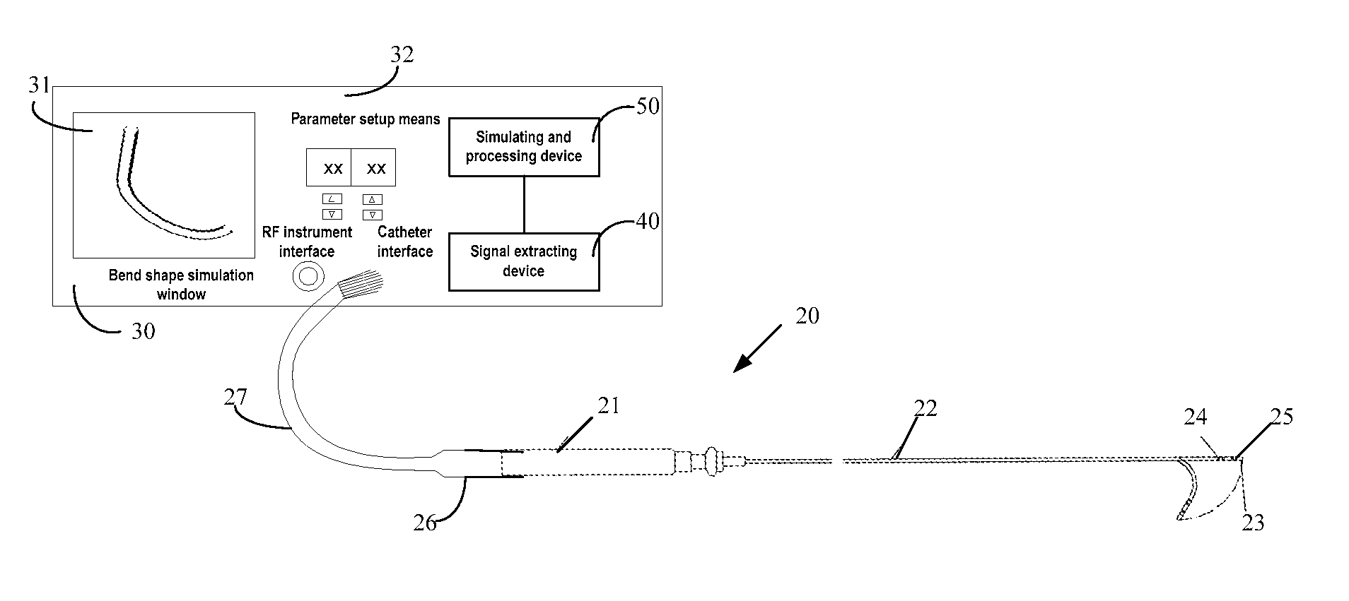
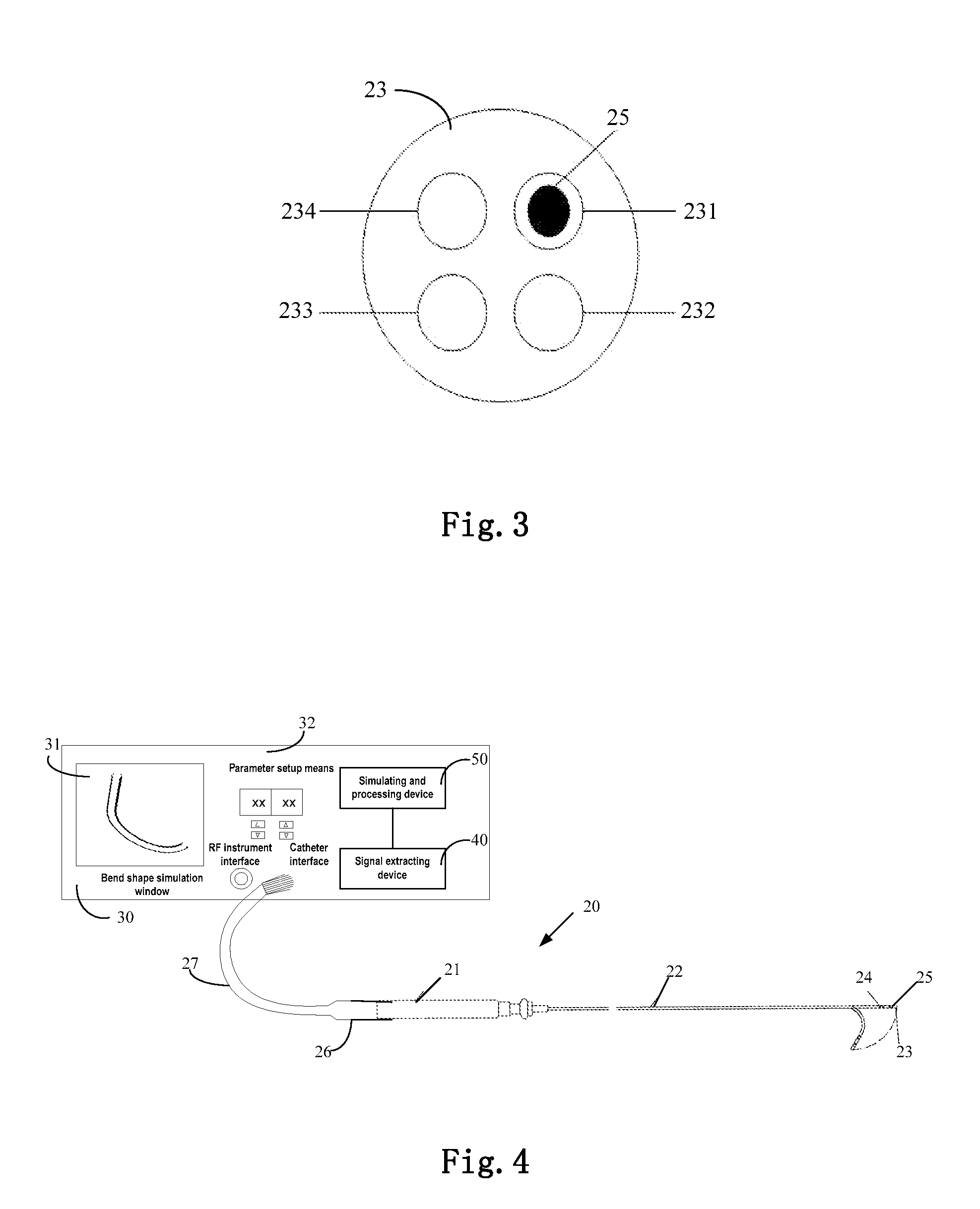
[0030]In the present invention, near the tip electrode of the catheter are arranged the magnetic sensors which traverse magnetic lines of force to generate an induced current. The position information and spatial information of the magnetic sensors are extracted based on the induced current information, and then the bend shape of the catheter is calculated in combination with the characteristic information of the catheter itself and displayed on the associated display device. As such, the operator can visually see the bend shape of the catheter in the heart during procedure. As compared with the prior art only displaying a position of the tip electrode of the catheter, the present invention can provide the operator with rich information of use condition of the catheter, thereby improving safety and effectiveness of the procedure.

Problems solved by technology

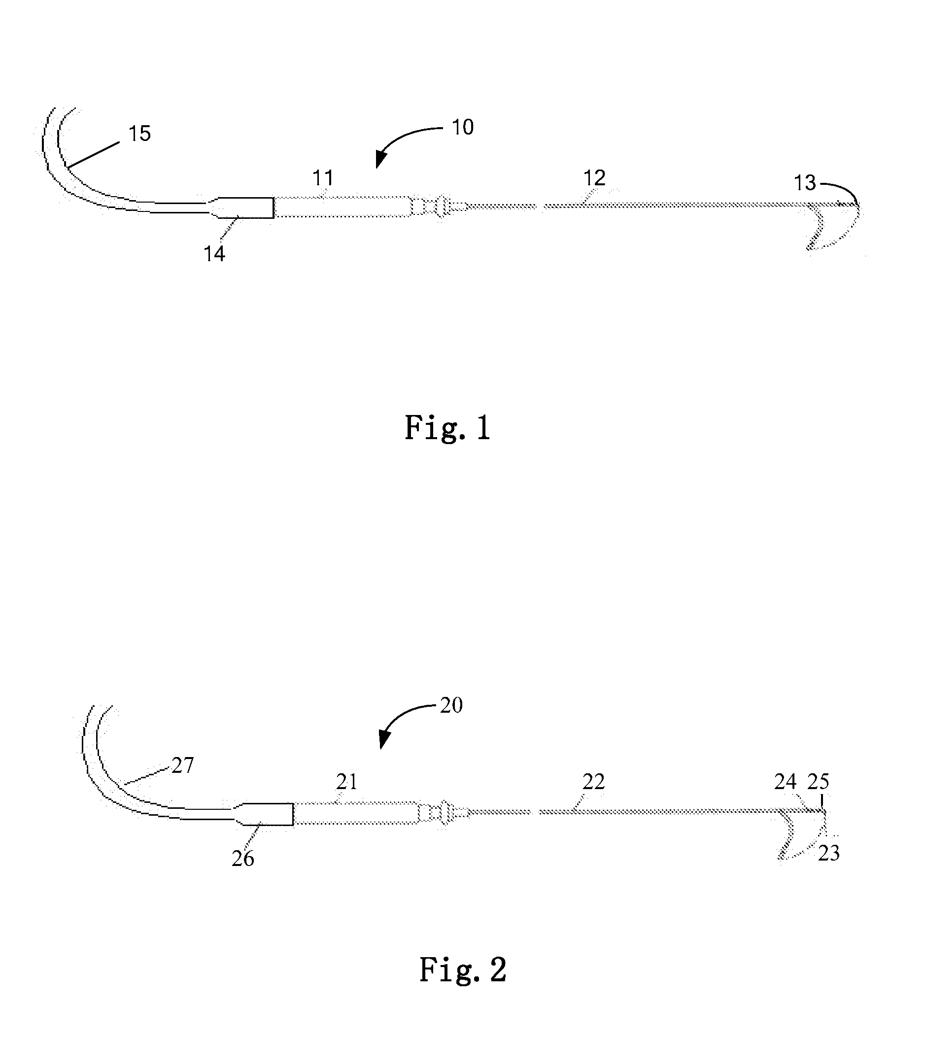
However, the three-dimensional anatomical image plotted by the present magnetic induction technology has a relatively big limitation since it can only display the position of the tip electrode 13 and can not display the bend shape of the catheter body 12 of the catheter 10 in the heart.
During the procedure, the operator can not visually see the bend shape of the catheter 10 in the heart, which brings inconvenience to the procedure, thereby dramatically reducing safety and controllability thereof.

Method used


Image

  • Method for simulating bend shape of catheter and magnetic induction catheter
  • Method for simulating bend shape of catheter and magnetic induction catheter
  • Method for simulating bend shape of catheter and magnetic induction catheter

Examples


Embodiment Construction

[0039]The above objects, features and advantages of the present invention will be apparent from the following detailed description with reference to the appended drawings and embodiments.

[0040]In the present invention, near the tip electrode of the catheter of the RF ablation catheter are arranged the magnetic sensors which traverse magnetic lines of force to generate induced current. The position information and directional information of the magnetic sensors are extracted based on the induced current information and then the bend shape of the catheter is calculated in combination with the characteristic information of the catheter itself and displayed on an associated display device. As such, the operator can visually see the bend shape of the catheter in the heart during procedure. As compared with the prior art, the present invention can bring convenience to the procedure and improve safety and controllability of the procedure.

[0041]FIG. 2 shows the schematic view of a catheter ...


PUM


Abstract

A method for simulating the bend shape of a catheter (20) includes providing at least two sensor elements (24,25) in the catheter (20), and said sensor elements (24,25) traverse magnetic line of force to generate induced current. Space information of the sensor elements (24,25) is extracted from the induced current information, and the bend shape of the catheter (20) is calculated according to aforementioned space information in combination with characteristic information of the catheter (20). A catheter (20) includes a catheter body (22), at least two magnetic sensors (24,25), a signal extracting device (40), and a simulating and processing device (50).

Description

TECHNICAL FIELD[0001]The present invention relates to the art of medical instruments, and more particularly to a method for simulating the bend shape of a catheter and a magnetic induction catheter.BACKGROUND OF THE INVENTION[0002]RF ablation catheters are mainly used for electrophysiological mapping, temporary cardiac pacing, RF ablating and the like of heart arrhythmia. FIG. 1 is a schematic view of a known RF ablation catheter which is generally indicated by a reference numeral 10 and comprises, among others, a catheter handle 11, a catheter body 12, a tip electrode 13, a connector 14 and an extension cable 15.[0003]In conventional catheter RF ablation treatment, by the catheter 10, the tip electrode 13 capable of transmitting RF energy may be transvenously or transarterially inserted into a human body and into a heart site under the monitoring of an X-ray TV to ablate a focus therein. When complex arrhythmia such as atrial fibrillation, atrial flutter and the like is treated, it...

Claims


Application Information

Patent Timeline
Patent Type & Authority Applications(United States)
IPC IPC(8): A61B18/18A61B5/296
CPCA61B5/06A61B5/6852A61B18/1492A61B19/5244A61M2205/3317A61B2019/5246A61B2019/5251A61M25/0127A61M2025/0166A61B2019/502A61B2034/102A61B2034/2046A61B34/20A61B2034/2051A61B5/062
Inventor LIU, DAOZHIYE, MINGGUO, JUNMINWANG, SHUN
Owner SHANGHAI MICROPORT EP MEDTECH CO LTD
Learn More