Multiple Slope or Multiple or Multiple Offset Tool Mechanism

a technology of offset spring and tool mechanism, which is applied in the direction of screwdrivers, metal-working devices, wrenches, etc., can solve the problems of less accurate, pretension of fasteners, and inability to adjust the speed of the fastener, so as to prolong the life of the product, improve the performance, and the effect of multiple slope operation

Inactive Publication Date: 2011-12-29
CREATIVE SYST & DESIGNS
View PDF6 Cites 14 Cited by
  • Summary
  • Abstract
  • Description
  • Claims
  • Application Information

AI Technical Summary

Benefits of technology

[0011]The present invention is generally characterized by placing a non-linear spring or combination of springs in the tool body to achieve multiple slope operation rather than using one single slope spring. The multiple slope configuration is superior in performance by moving closer to the ideal case of 0% error in operation. This low-error performance can be maintained with multiple slope configurations over the entire range of operation. The multiple slope configuration prolongs the life of the product as well as decreasing the need for recalibration as well as increasing the range of operation.

Problems solved by technology

The torque is often applied to the head of the fastener, which causes the fastener to stretch.
This stretch results in pretension of the fastener, which is the force that holds the joint together.
The mechanical types are generally less expensive and are not as accurate as more expensive electronic torque wrenches.
This single-slope mechanism limits the attainable accuracy of the current clickers.
Another problem with the current clickers is that they tend to lose their accuracy quickly and require recalibration often.
This leads to increased maintenance cost and down time.
Non-linear spring combinations using series and parallel springs with different “K” factors (spring constant in pounds per inch) are known in the art; however, they have not been used in torque wrenches and like tools.

Method used


Image

  • Multiple Slope or Multiple or Multiple Offset Tool Mechanism
  • Multiple Slope or Multiple or Multiple Offset Tool Mechanism
  • Multiple Slope or Multiple or Multiple Offset Tool Mechanism

Examples


Embodiment Construction

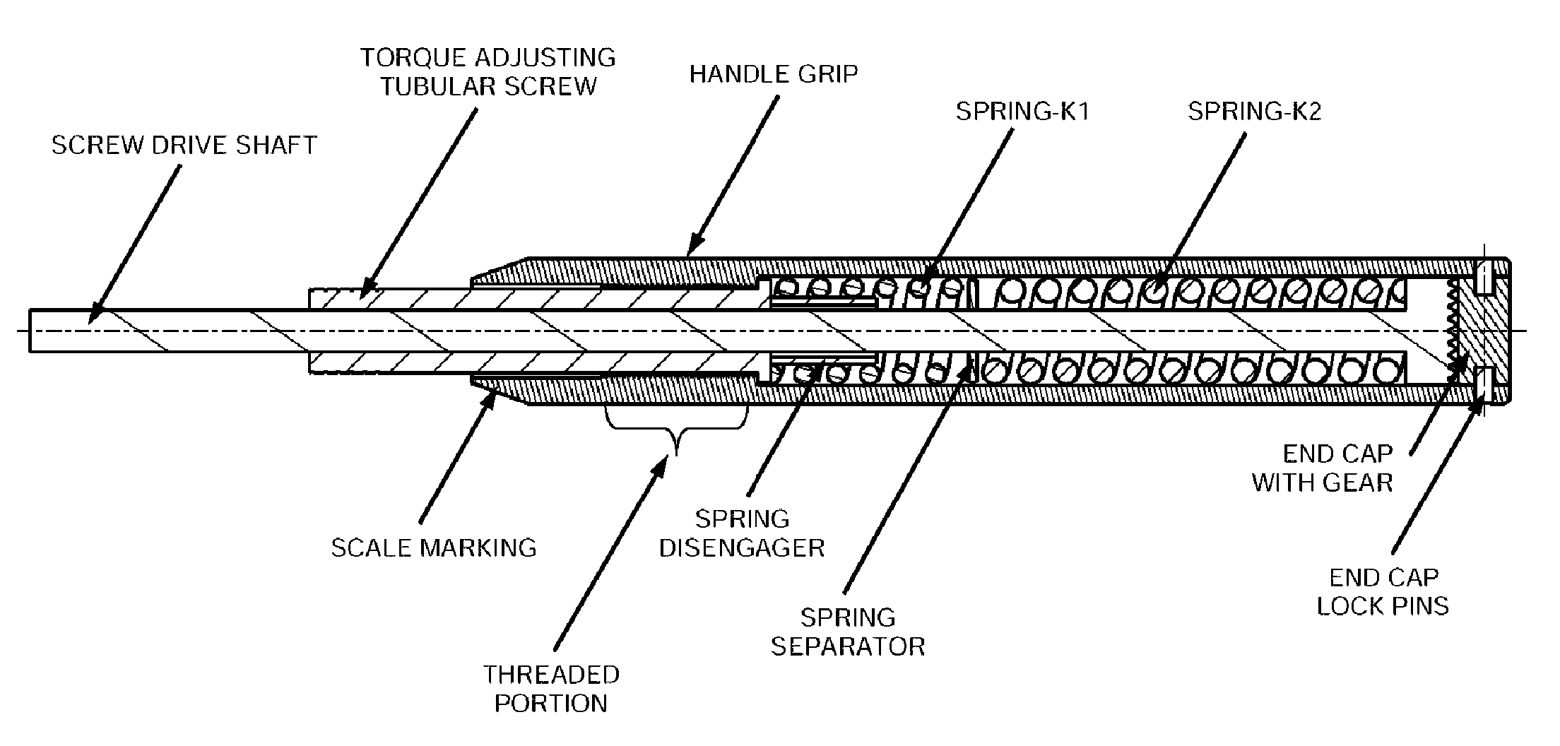
[0032]The present invention generally places multiple slope and / or multiple offset spring mechanisms in torque wrenches and like tools. This leads to increased accuracy, increased useful life of the product, decreased need for recalibration and increased range of operation.

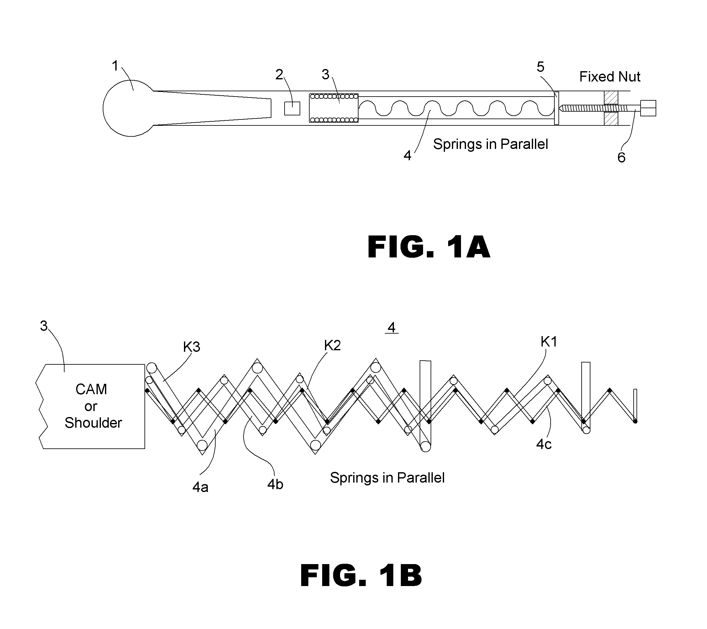
[0033]Turning to FIGS. 1A-1B, a tool handle can be seen in FIG. 1A with a diagram of a possible spring combination in FIG. 1B. A tensor 1 resides in front of a pivot block 2 and a cam 3. Several springs in parallel 4 are compressed by a push plate 5 that is driven by the adjusting screw 6. Schematically, in FIG. 1B, the spring mechanism 4 can be seen to include, in this case, three springs 4a, 4b and 4c arranged in parallel. The first zone of engagement only involves spring 4c with slope K1. In this zone, spring 4c acts linearly. At some point in the engagement, spring 4b also becomes engaged in parallel with spring 4c. In this second zone, the slope is K1+K2 (the two springs in parallel). Finally, the third sprin...


PUM

PropertyMeasurementUnit
torqueaaaaaaaaaa
diameteraaaaaaaaaa
inner diameteraaaaaaaaaa

Abstract

Use of multiple-slope and/or multiple-offset mechanism or equivalent to address the issues with current mechanical clickers that have single-slope spring mechanism. The varying-slope can be a continuously varying-slope non-linear spring, or a combination of discretely varying multiple-slope springs. This invention is useful for clicker type torque wrenches, clicker type torque screw drivers, beam type torque wrenches, beam type torque screw drivers and shock absorbers. The present invention is equally applicable to clickers that click in both the CW (clockwise) and CCW (counterclockwise) directions or clickers that click only in one direction. The invention is generally characterized by placing a non-linear spring or combination of springs in the tool body to achieve multiple slope operation rather than using one single slope spring. The multiple slope configuration is superior in performance by moving closer to the ideal case of 0% error in operation. This error performance can be maintained with multiple slope configurations over the entire range of operation. The multiple slope configuration prolongs the life of the product as well as decreasing the need for recalibration as well as increasing the range of operation.

Description

[0001]This application is related to and claims priority from U.S. Provisional patent application Nos. 61 / 398,353 filed Jun. 24, 2010 and 61 / 403,686 filed Sep. 20, 2010. Applications 61 / 398,353 and 61 / 403,686 are hereby incorporated by reference.BACKGROUND[0002]1. Field of the Invention[0003]The present invention relates generally to self-adjusting mechanisms used in torque wrenches and torque screwdrivers, and more particularly to multiple-slope and / or multiple-offset spring mechanisms that exhibit non-linear behavior for use in such tools.[0004]2. Description of the Prior Art[0005]In many applications such as torque wrenches, shock absorbers, etc. the ability to adjust the characteristic behavior of the mechanism as the applied load is varied will enable the new generation of mechanisms. Torque wrenches are commonly used to tighten fasteners to a desired torque. The fasteners used to assemble performance critical components require tightening to a specific ‘torque’ level to introd...

Claims


Application Information

Patent Timeline
Patent Type & Authority Applications(United States)
IPC IPC(8): B25B23/159B23P11/00
CPCY10T29/49826B25B23/1427Y10T29/49718
Inventor ANJANAPPA, MUNISWAMAPPALI, SIBAIG, MUNEERANJANAPPA, ASHWINI
Owner CREATIVE SYST & DESIGNS
Why Eureka
Try Eureka