
X-ray optical systems with adjustable convergence and focal spot size

a technology of optical systems and focal spots, applied in the field of x-ray optical systems, can solve the problems of inefficient and uneconomical use of different optics, limiting the applicability of such optics in many applications, and changing the optical elements

Active Publication Date: 2011-12-29
RIGAKU INNOVATIVE TECH
View PDF3 Cites 9 Cited by
  • Summary
  • Abstract
  • Description
  • Claims
  • Application Information

AI Technical Summary

Benefits of technology

[0018]In satisfying the above need, as well as overcoming the enumerated drawbacks and other limitations of the related art, at least one embodiment of the present invention prov...

Problems solved by technology

However, for focusing multilayer optics, the convergence angle of such optics limits their applicability in many applications, since for an application, a different convergence angle, and thus a different optic, is often needed for different types of samples.
Using different optics is inefficient and uneconomical since changing the optical elements is a costly and time consuming drain on researchers, in particular, and industry, in general.
However, the alignment and adjustment of these mirrors are very time consuming and difficult to perform, and any imperfection in the alignment or adjustment of the optic degrades the system performance.
Moreover, this approach is not generally applicable to multilayer optics, because of the inability of the variable bent multilayer mirrors to satisfy both the Bragg condition and geometric condition, which have to be satisfied simultaneously.
Therefore, such optics cannot be fully optimized for the best performance at the different wavelengths.
If an x-ray source with a particular target material selected to operate at the first wavelength irradiates the multiple corner optic assembly, the corner configured to reflect x-rays of the first wavelength will reflect radiation of the target characteristic emission line, or monochromatic radiation, and the second corner configured to reflect x-rays of the second wavelength will collect and reflect some portion of continuous radiation with a wavelength around its characteristic emission line, thus creating unwanted background radiation.

Method used


Image

  • X-ray optical systems with adjustable convergence and focal spot size
  • X-ray optical systems with adjustable convergence and focal spot size
  • X-ray optical systems with adjustable convergence and focal spot size

Examples


Embodiment Construction

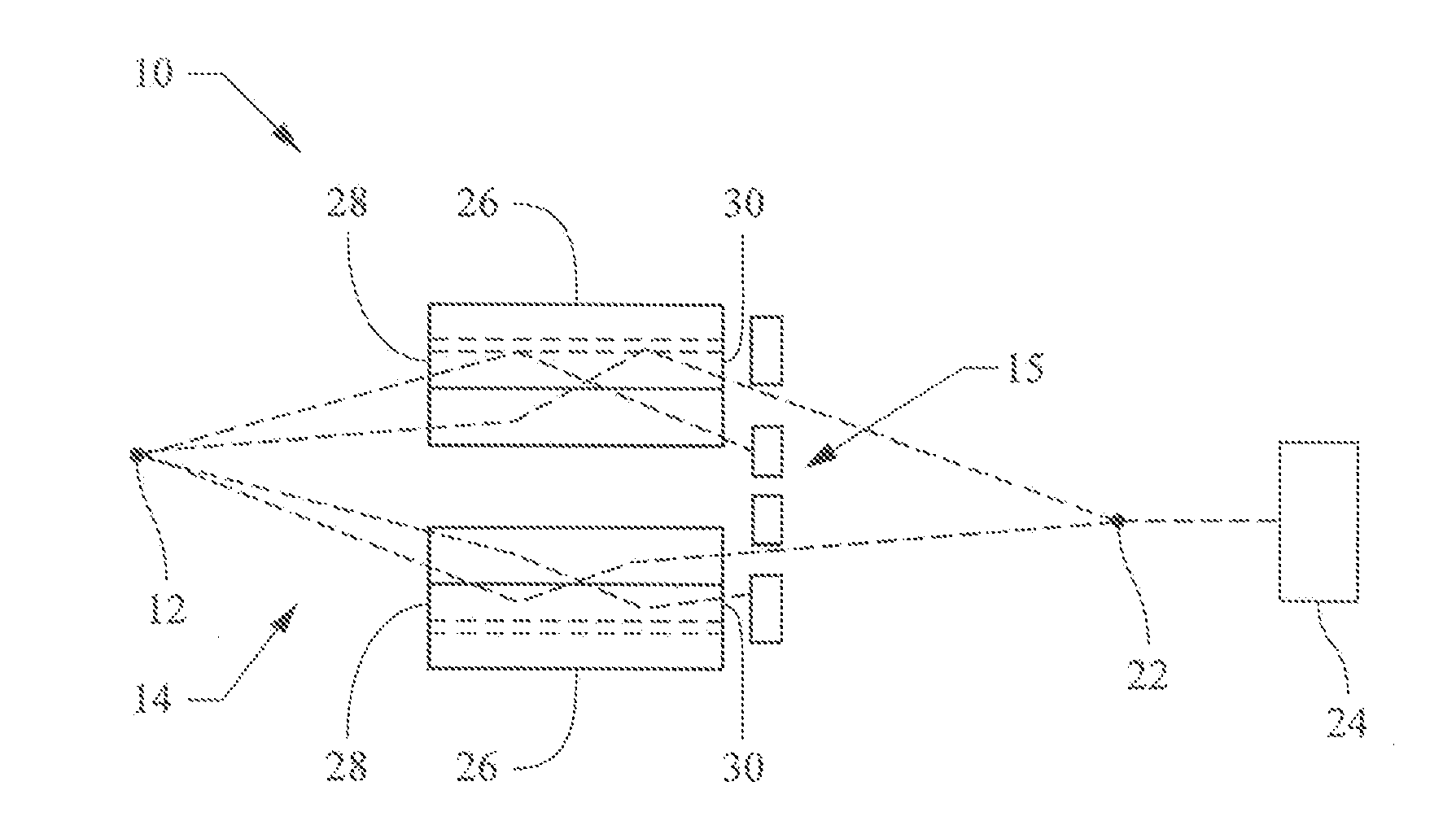
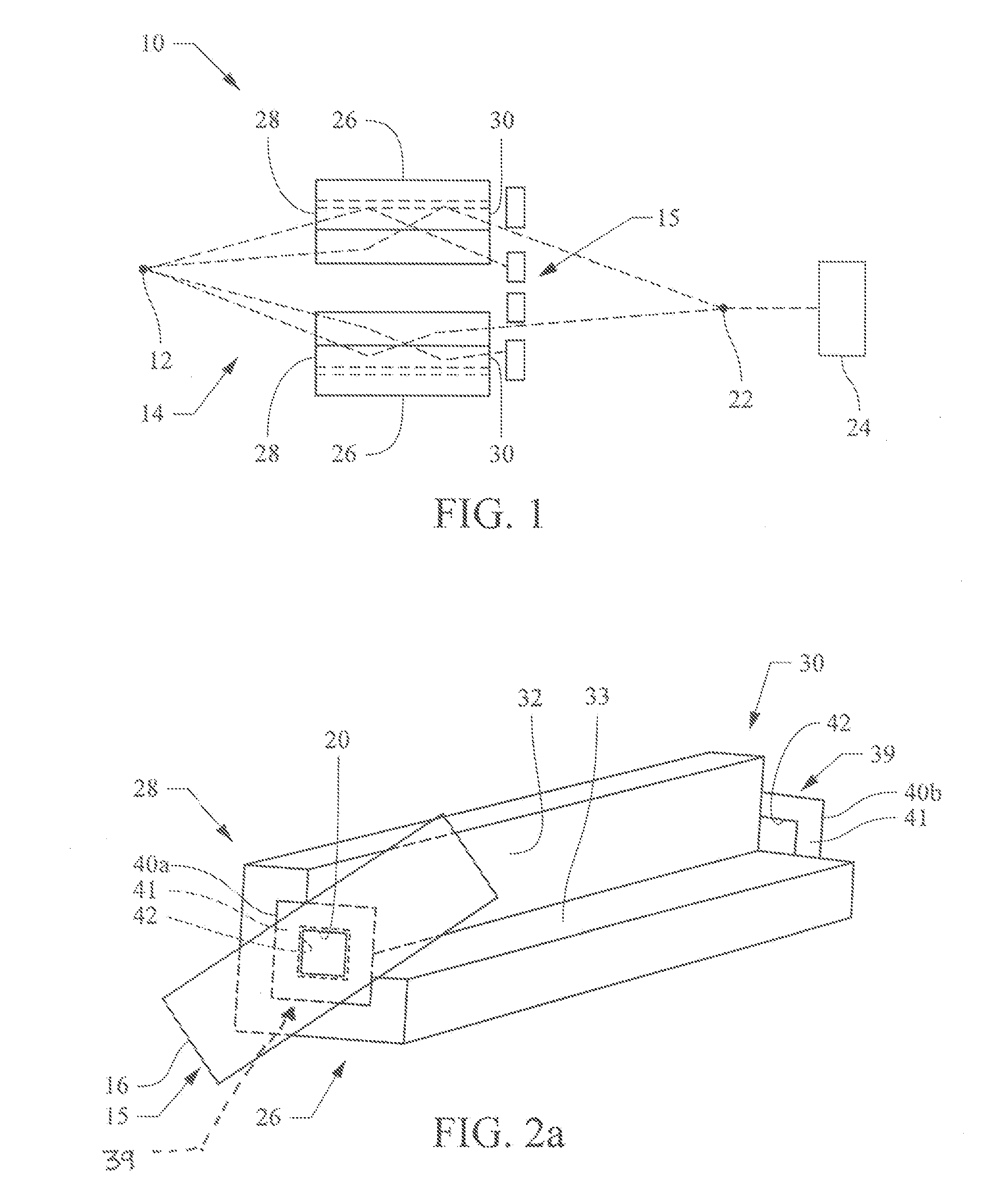
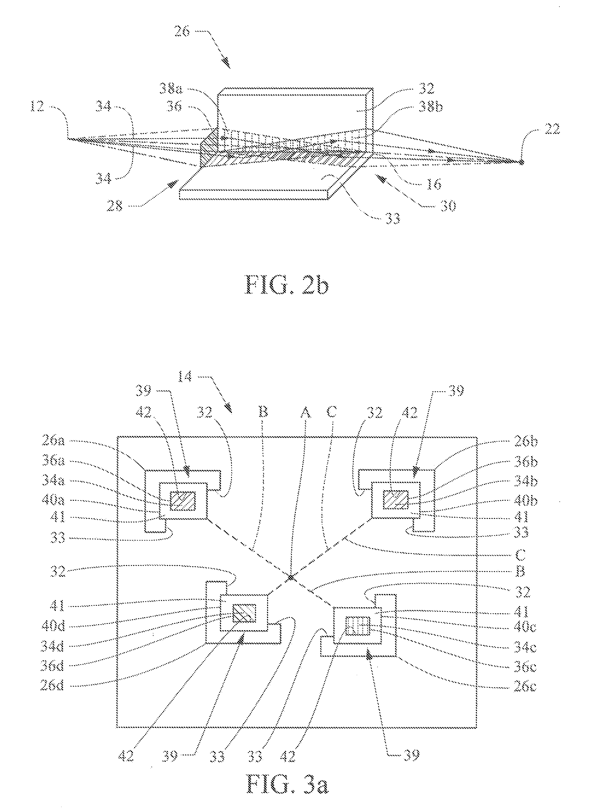
[0036]In accordance with the teachings of the present invention, an improved x-ray optical system incorporates a movable, i.e., adjustable, aperture assembly that enables a user to easily and effectively adjust the convergence of an incident beam of x-rays or the optic focal spot size. In doing so, the flux and resolution of the x-ray system can be optimized by using an optic having a high degree of convergence for a range of potential measurements, and then selecting a convergence for a particular measurement by adjusting the aperture. Thus, the flux and resolution are easily adjusted and optimized for the needs of different applications or measurements, and hence the efficiency of the overall optical system is increased.

[0037]In accordance with further teachings of the present invention, an improved x-ray optical system capable of adjusting beam convergence and optic focal spot size, as well as being capable of conditioning x-rays of different wavelengths while minimizing unwanted...


PUM


Abstract

An x-ray optical system includes a multiple corner optic assembly including an adjustable aperture assembly located in close proximity to the optic assembly. The adjustable aperture assembly enables a user to easily and effectively adjust the convergence of an incident beam of x-rays or the optic focal spot size. The adjustable aperture assembly may further enable a user to condition x-rays of one wavelength and block x-rays of another wavelength and thereby reduce the amount of background radiation exhibited from x-rays of more than one wavelength.

Description

BACKGROUND[0001]1. Field of the Invention[0002]The present invention relates to an x-ray optical system. More particularly, the present invention relates to an x-ray optical system which conditions an x-ray beam.[0003]2. Description of Related Art[0004]X-ray optics are used in many applications such as x-ray diffraction analysis and spectroscopy that require the directing, focusing, collimation, or monochromatizing of x-ray energy from an x-ray source. Researchers have long employed focusing x-ray optics in x-ray diffraction experiments to increase the flux incident on the sample and hence to increase the signal to noise ratio of radiation received by a detector.[0005]A focusing optic increases the flux by directing a large number of photons through the sample. However, for focusing multilayer optics, the convergence angle of such optics limits their applicability in many applications, since for an application, a different convergence angle, and thus a different optic, is often need...

Claims


Application Information

Patent Timeline
IPC IPC(8): G21K1/06
CPCB82Y10/00G21K1/04G21K2201/067G21K2201/064G21K1/062
Inventor VERMAN, BORIS
Owner RIGAKU INNOVATIVE TECH
Learn More