Quantum cryptography service network implementation structure

Active Publication Date: 2011-12-29
CHUNGHWA TELECOM CO LTD
View PDF4 Cites 36 Cited by
  • Summary
  • Abstract
  • Description
  • Claims
  • Application Information

AI Technical Summary

Benefits of technology

[0016]Alice and Bob transmit and receive the photons through a single mode fiber, which is called a quantum channel. The photons of a specific wavelength are susceptible to light pulses of the same wavelength. Therefore, in the quantum channel, only light pulses of different wavelength can co-exist. On the other hand, a fiber used for traditional fiber communication can have a specific wavelength saved for Alice and Bob to act as a quantum channel, eliminating the need for building a fiber for the quantum channel. However, the energy of the light pulse of the traditional fiber communication is too high for the photons. During operation or maintenance of the traditional fiber communication equipment, it is possible to damage Alice or Bob of the quantum channel of the same fiber.
[0021]The quantum cryptography service network implementation technique can let different pairs of Alice / Bob of separate network segments jointly operate to implement the quantum key service network; if it is to relay a quantum key to different segments, it is possible to replace the AB-type quantum key generator 201 with a combination-type quantum key generator in FIG. 4 to relay the quantum key. In this way it is possible to extend the reach of the quantum key and to expand the network topology; so the surrounding telecommunication networking system can use the quantum key to encrypt / decrypt the traffic of the whole telecommunication network. Besides, it is possible to use the quantum key to encrypt / decrypt the traffic end to end and across different regions.
[0026]In summary, the quantum key terminal equipment of each node in the quantum key network uses a common random number generator which complies with the BB84 Protocol or its derivatives to generate the quantum key which is consistent between adjacent nodes. The original BB84 Protocol can only guarantee the consistency of the quantum key content of the sender Alice and the receiver Bob. In the present invention, the adjacent nodes such as Alice 1 and Bob 1, Bob 1 and Alice 2, and Alice 2 and Bob 2 can share the quantum key with consistent content. For example, in FIG. 2, the A-type quantum key generator 210 of Site A and the AB-type quantum key generator 201 of Site B are connected through the quantum channel 211. The AB-type quantum key generator 201 of Site B and the B-type quantum key generator 220 of Site C are connected through the quantum channel 221 and so forth. Therefore, in the quantum key network, any sender at the head end will have a consistent quantum key with the receiver at the tail end. So the quantum key network topology could be a serial type, or a star type, or their combination; and in the star configuration no optical switch is required in the quantum channel. In this structure, it is possible to avoid the insertion loss or the accumulated insertion loss of the serial type quantum channel in the quantum cryptography service network structure in the telecommunication network.

Problems solved by technology

However, since the routing path is open to the public, the encrypted traffic could be hacked by a third party and sooner or later it could cause the encryption codes to be resolved by a quantum computer.

Method used


Image

  • Quantum cryptography service network implementation structure
  • Quantum cryptography service network implementation structure
  • Quantum cryptography service network implementation structure

Examples


Embodiment Construction

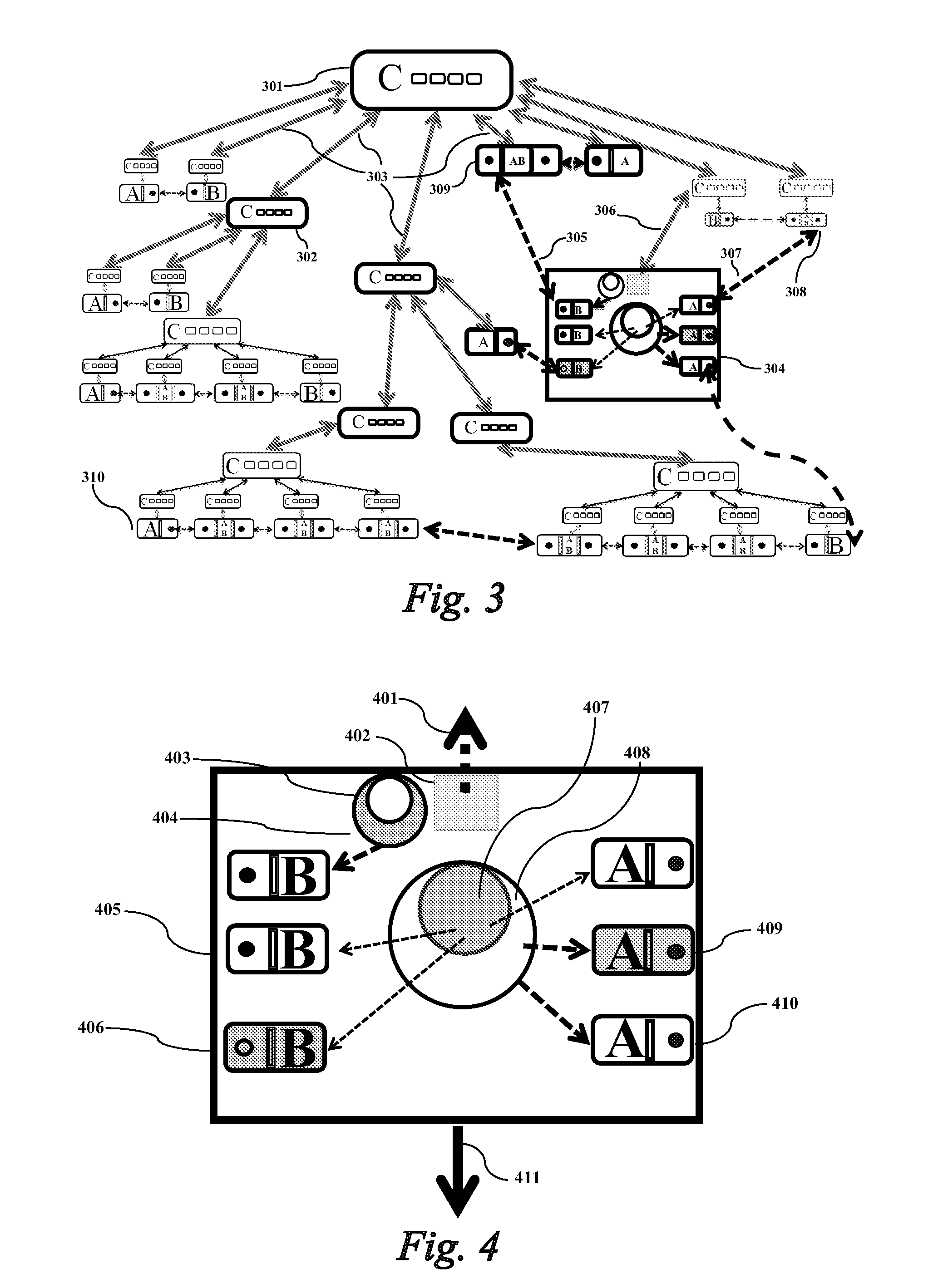
[0106]The present invention provides a quantum cryptography service network implementation technique, wherein the network comprises: (1) a hierarchically central clock signal synchronous network having an extremely accurate clock signal generation source to transmit the clock signal to a lower level through a dedicated synchronous clock signal channel. Numerous hierarchically distributed derivative-type synchronous clock signal generators receive and re-generate the clock signal for next-level equipment of the same premises. The configuration is shown in FIG. 3. The source-type synchronous clock signal generator 301 is an extremely accurate clock signal generator and acts as the reference clock signal source for the whole clock signal synchronous network of the carrier; the clock signal is distributed through the synchronous clock signal channel 303 to each central office and then distributed to the lower level; the derivative-type synchronous clock signal generator 302 receives and...


PUM


Abstract

In order to overcome the limitation of the prior art quantum key terminal equipment not being able to operate across different segments, the present invention discloses a quantum cryptography service network implementation technique to let a point-to-point quantum key equipment in one segment be redesigned to cooperate with other quantum key equipment in other segments to form a quantum key service network. As opposed to the prior art technique of having each segment generates its own quantum key, the present invention can map one pair of quantum key equipment with another pair of quantum key equipment, or map multiple pairs of quantum key equipment connected in series to have quantum keys entirely or partly shared by the quantum key equipment. Therefore, the generated quantum keys can be used across different segments. Each node in the quantum key service network can provide the quantum key to nearby telecommunication equipment in the telecommunication network of the same premises.

Description

BACKGROUND OF THE INVENTION[0001]1. Field of the Invention[0002]The present invention relates to a quantum key service network implementation technique using a quantum cryptography technique so as to let a private local area network or a telecommunication carrier create a multi-path quantum cryptography service network. Compared with a traditional telecommunication service network, the quantum cryptography service network uses quantum keys provided by quantum key terminal equipment in the quantum key service network to encrypt / decrypt the incoming / outgoing traffic for either end of the network to ensure safe communication.[0003]In order to achieve the above objects, the quantum key service network is managed by a quantum key server, and various types of quantum key terminal equipment and their combination can provide quantum keys to be used by telecommunication networking equipment such as a router. Therefore, the telecommunication network is upgraded to become a telecommunication n...

Claims


Application Information

Patent Timeline
Patent Type & Authority Applications(United States)
IPC IPC(8): H04K1/00
CPCH04L9/12H04L9/0855
Inventor YEH, TZUOH-CHYAUTSAI, I-MING
Owner CHUNGHWA TELECOM CO LTD
Why Eureka
Try Eureka