Passive optical network protection method, switchover control device, and passive optical network protection system

a technology of optical network protection and switchover control, applied in multiplex communication, wavelength-division multiplex systems, instruments, etc., can solve the problems of high network construction cost, hindered access to and high access to enterprise users and dedicated line users of pon. , to achieve the effect of facilitating the application of pon technology, saving network cost, and smooth communication

Active Publication Date: 2011-12-29
HUAWEI TECH CO LTD
View PDF2 Cites 43 Cited by
  • Summary
  • Abstract
  • Description
  • Claims
  • Application Information

AI Technical Summary

Benefits of technology

Embodiments of the present application provide a PON protection method, a switchover control device, and a PON protection system, so that one protection OLT may be used to protect multiple working OLTs.
In embodiments of the present application, a protection OLT is connected to optical links of at least two working OLTs through the switchover control device. When a working OLT or working optical link fails, the switchover control device replaces the working OLT through the protection optical link, so as to ensure smooth communication. In addition, compared with the prior art, by using the networking mode of multiple working OLTs and one protection OLT, the embodiments of the present application greatly save the networking cost and facilitates the application of the PON technology.

Problems solved by technology

Though the solution may protect the feeder fiber and OLT, each OLT needs a protection OLT and the network construction cost is high.
As a result, access applications of enterprise users and dedicated line users of the PON are hindered.

Method used


Image

  • Passive optical network protection method, switchover control device, and passive optical network protection system
  • Passive optical network protection method, switchover control device, and passive optical network protection system
  • Passive optical network protection method, switchover control device, and passive optical network protection system

Examples


embodiment 1

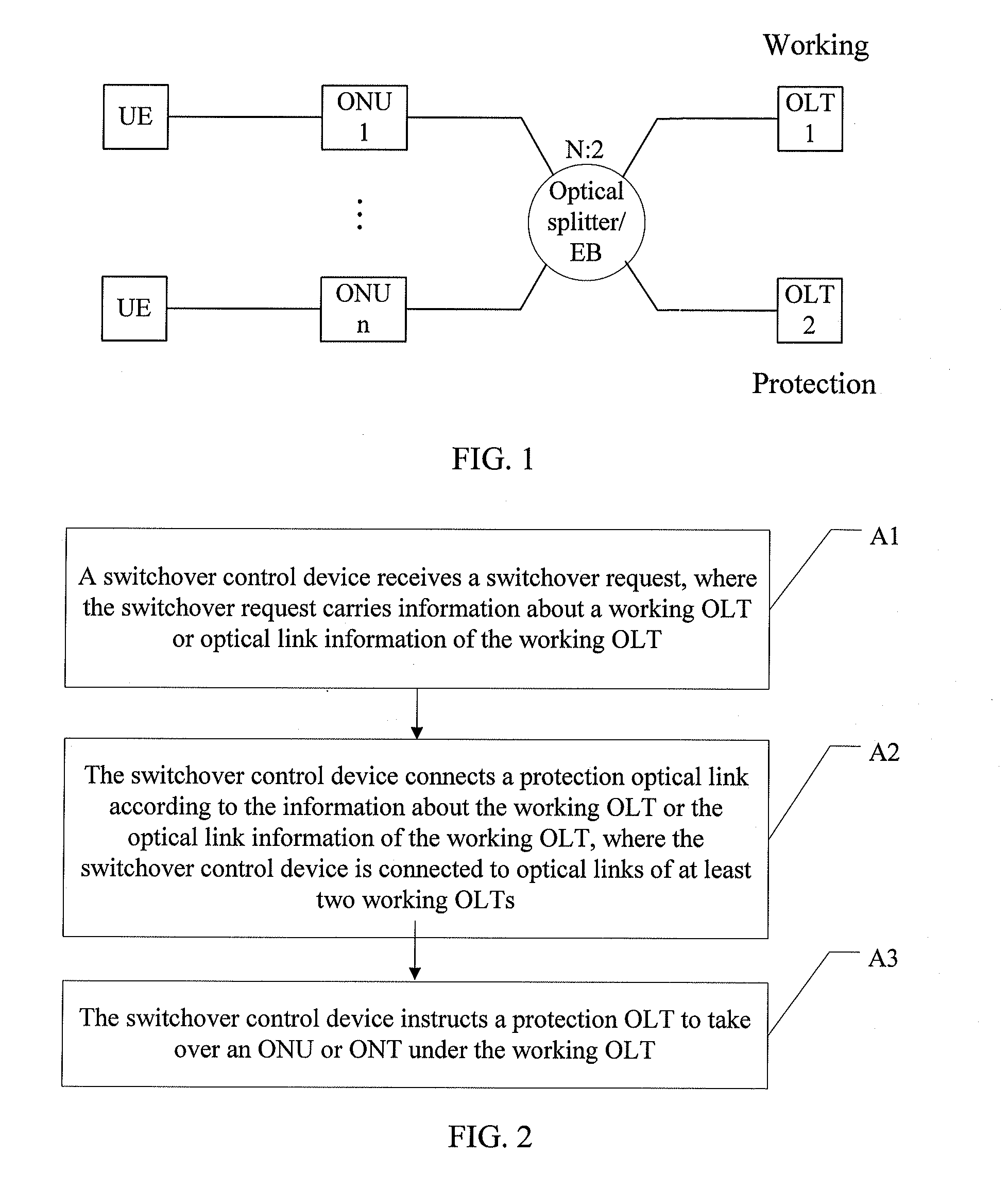
A PON protection method is provided. As shown in FIG. 2, the method includes the following steps:

A1. A switchover control device receives a switchover request. The switchover request may carry information about a working OLT (such as a communication interface of an optical splitting device corresponding to the working OLT) or optical link information of the working OLT (such as a communication interface of an optical splitting device corresponding to the optical link of the working OLT).

In this embodiment, when a protection OLT learns that the working OLT or the optical link of the working OLT fails, the protection OLT sends a switchover request to the switchover control device. It is appreciated that the switchover request may also be sent by the working OLT or an ONU or EB under the working OLT to the switchover control device. The switchover may be triggered in multiple modes, and therefore whichever device triggers the switchover does not constitute a limitation on the present a...

embodiment 2

A PON protection method is provided. As shown in FIG. 8, the method includes the following steps:

B1. A switchover control device monitors optical transmission data from an ONU or ONT port by using an optical splitting device connected to an optical link of a working OLT.

In this embodiment, the switchover control device and the optical splitting device on the optical link of the working OLT are connected through an OD; the OD monitors the uplink optical transmission data from the ONU or ONT port through the optical splitting device connected to the optical link of the working OLT.

B2. The switchover control device determines whether the working OLT or the optical link of the working OLT fails according to the monitoring result, and if the working OLT or the optical link of the working OLT fails, a protection optical link is connected, where the switchover control device is connected to optical splitting devices on optical links of at least two working OLTs.

In this embodiment, if the s...

second embodiment

The second embodiment differs from the first embodiment in that: an apparatus for detecting the working optical link is added to the switchover control device; by detecting the uplink optical signals on the ONU port of the switchover control device, the status of the working optical link or working OLT may be obtained and a switchover is performed according to the status. In this embodiment, the switchover function may be implemented through improvement on the EB.

FIG. 9 (a), FIG. 9 (b), FIG. 9 (c), and FIG. 9 (d) are schematic structure diagrams of improved special EBs. The EB in FIG. 9 (a) includes: an OD, an optical switch, a tap, an optical splitter, an embedded ONT, an LC, and an OA or OEO transceiver.

The OD is equivalent to an OLT receiver, and is configured to detect uplink optical signals and parse uplink optical transmission data. The specific function is: monitoring uplink optical transmission data from the ONU port; if no uplink transmission data is monitored within a cert...


PUM


Abstract

The present invention discloses a passive optical network (PON) protection method, a switchover control device, and a PON protection system. In embodiments of the present invention, a protection optical line terminal (OLT) is connected to optical links of at least two working OLTs through the switchover control device; when a working OLT or working optical link fails, the switchover control device replaces the working OLT through the protection optical link, thus ensuring smooth communication. In addition, by using the networking mode of multiple working OLTs and one protection OLT, the embodiments of the present invention greatly saves the networking cost and facilitates the application of the PON technology.

Description

FIELD OF THE APPLICATIONThe present application relates to optical communication technologies, and in particular, to a passive optical network (PON) protection method, a switchover control device, and a PON protection system.BACKGROUND OF THE APPLICATIONThe PON (Passive Optical Network, PON) technology is a point to multi-point (P2MP) optical access technology. A PON includes an optical line terminal (Optical line terminal, OLT), an optical splitter (Optical splitter) or extender box (Extender Box, EB), optical network units (Optical Network Unit, ONUs) or optical network terminals (Optical Network Terminal, ONTs), and optical fibers connecting these devices. The OLT, as a device at the central office end, is connected to the optical splitter or EB through a feeder fiber, and the optical splitter or EB is connected to each ONU through a separate drop fiber. A feeder fiber exists between the optical splitter or EB and the OLT, and several drop fibers exist between the optical splitte...

Claims


Application Information

Patent Timeline
Patent Type & Authority Applications(United States)
IPC IPC(8): H04B10/08H04J14/02H04J14/00H04B10/038
CPCH04J14/0227H04J14/0282H04J14/0283H04J14/0286H04J14/0287H04J14/0291H04J14/0267H04L41/0213H04L41/0663H04L43/0811H04Q11/0067H04Q2011/0081H04J14/0297
Inventor ZHENG, RUOBIN
Owner HUAWEI TECH CO LTD
Why Eureka
Try Eureka