
Membrane-electrode assembly for fuel cell, fuel cell and manufacturing the method thereof

Inactive Publication Date: 2011-12-29
SAMSUNG ELECTRO MECHANICS CO LTD
View PDF0 Cites 4 Cited by
  • Summary
  • Abstract
  • Description
  • Claims
  • Application Information

AI Technical Summary

Benefits of technology

[0008]The present invention has been made in an effort to provide a membrane-electrode assembly for a fuel cell and a fuel cell in which contact surface resistance between the interfaces is minimized while each interface is closely in contact with each other.
[0009]Further, the present invention has been made in an effort to provide a membrane-electrode assembly for a fuel cell and a fuel cell capable of minimizing current collecting resistance and loss at the time of collecting current.

Problems solved by technology

However, when the gas diffusion layer and the electrolyte layer are each separately manufactured and bonded as described above, however, a high-temperature and high-pressure hot pressing process should be conducted in order to reduce interface resistance between the bonded layers and a contact status of each interface is deteriorated causing degradation in the performance.
In addition, it costs a great deal to manufacture an electrolyte membrane generally used as an electrolyte layer and a pretreatment process of the electrolyte membrane is required, thereby being disadvantageous in expense and mass production.

Method used


Image

  • Membrane-electrode assembly for fuel cell, fuel cell and manufacturing the method thereof
  • Membrane-electrode assembly for fuel cell, fuel cell and manufacturing the method thereof
  • Membrane-electrode assembly for fuel cell, fuel cell and manufacturing the method thereof

Examples


example 1

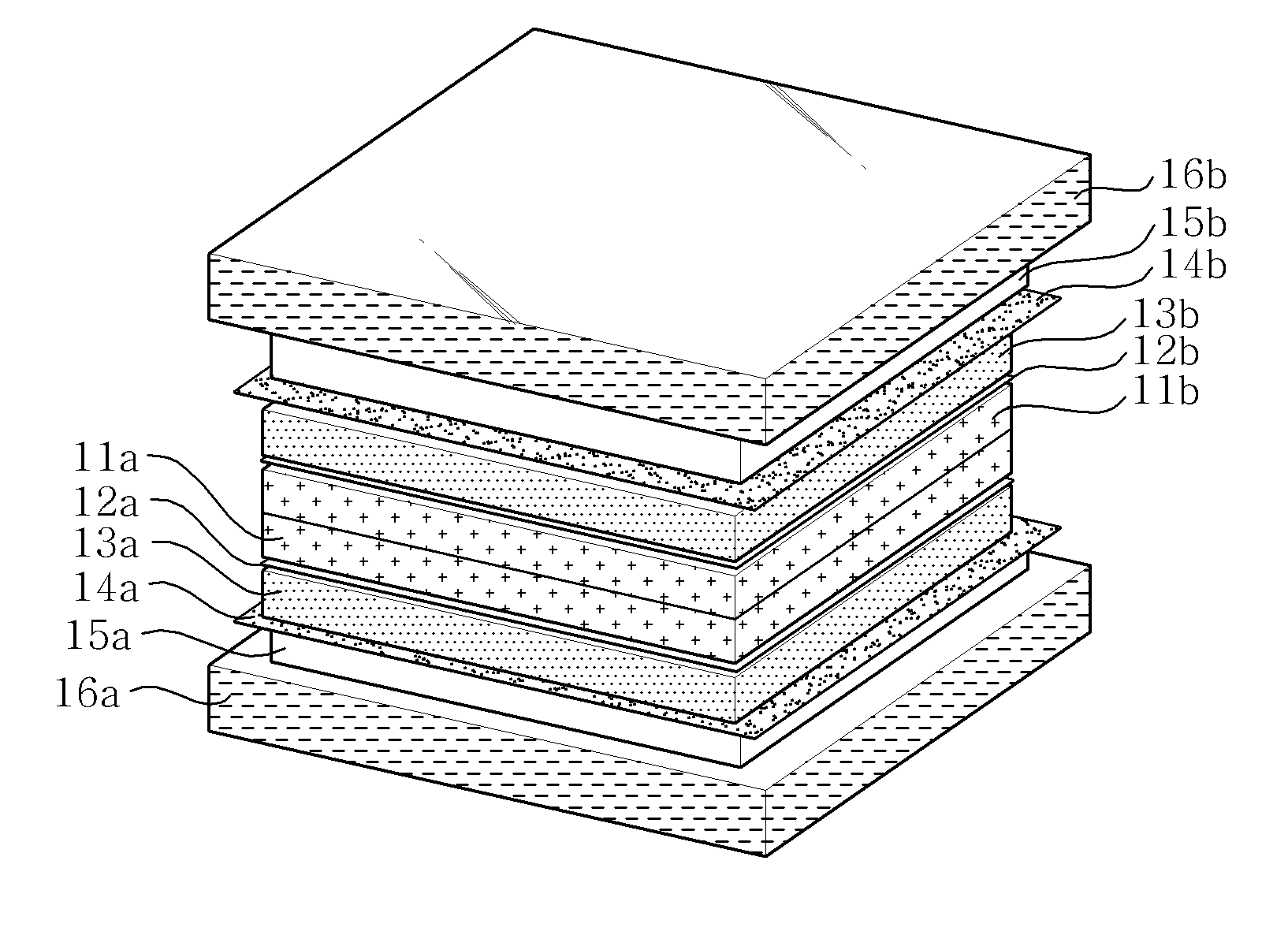
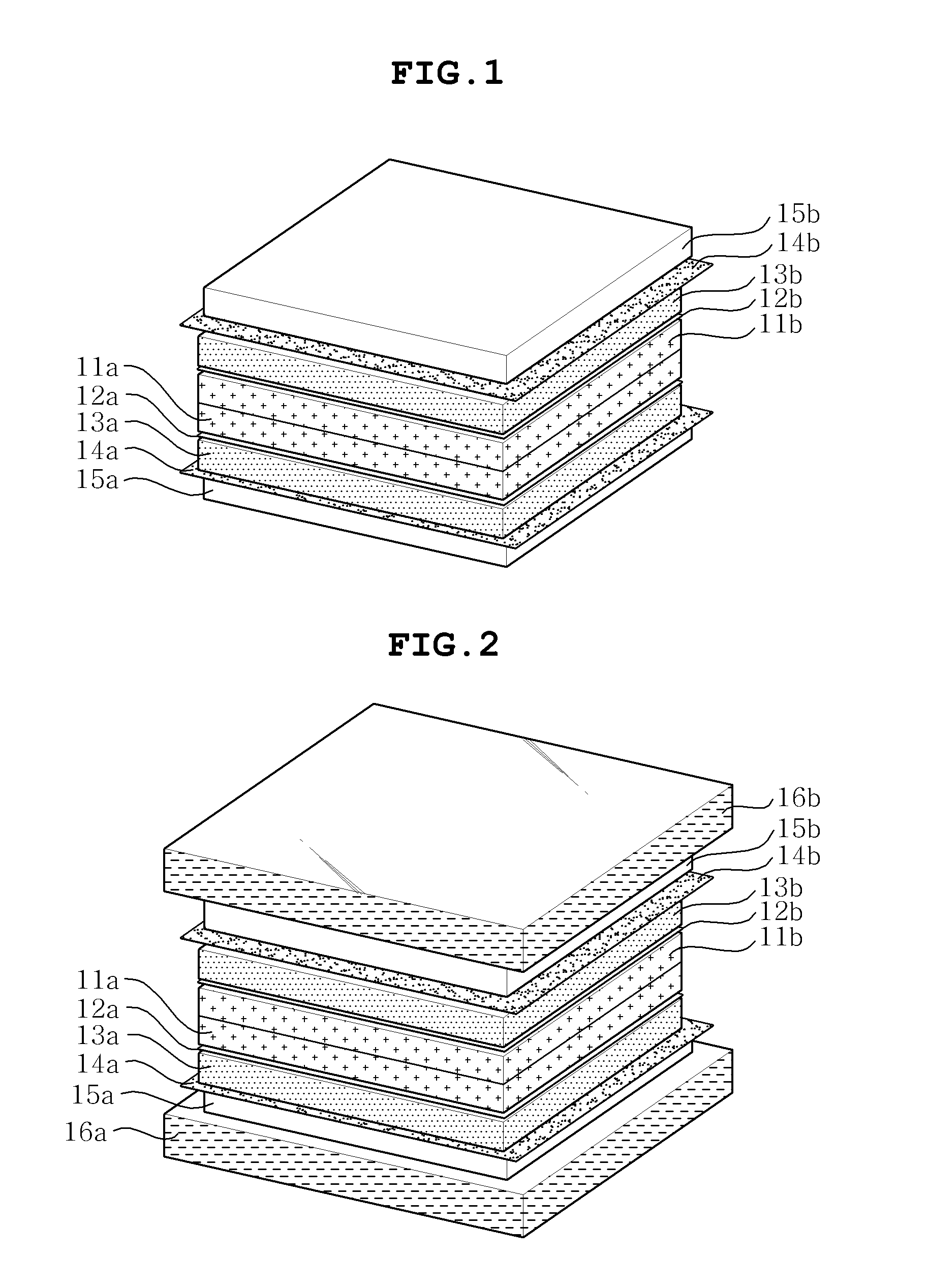
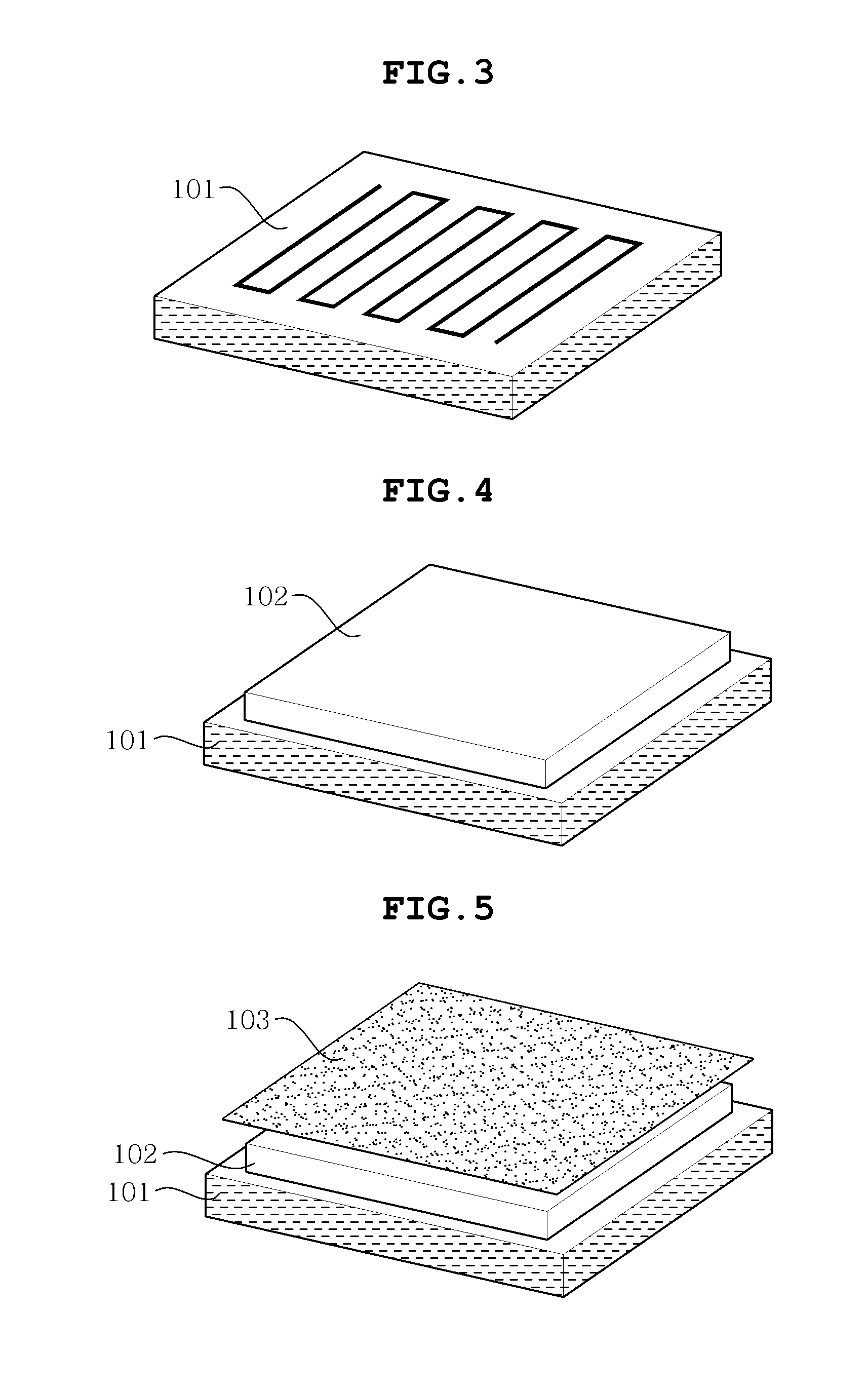
[0076]As shown in FIGS. 3 to 8, the first gas diffusion layer 102, the first micro current collecting layer 103, the first micro porous layer 104, and the first catalyst layer 105 (formed by the catalyst ink in which the catalyst material for the anode is dispersed) are sequentially formed on the first separator 101 and then, the electrolyte solution (for example, trade nameNafion dispersion solution”) is applied to the first catalyst layer 105 to form the first electrolyte layer 106, thereby preparing the laminate for the first electrode (anode).

[0077]Next, as shown in FIG. 9, the second gas diffusion layer 202, the second micro current collecting layer 203, the second micro porous layer 204, and the second catalyst layer 205 (formed by the catalyst ink in which the catalyst material for the anode is dispersed) are sequentially formed on the second separator 201 and then, the electrolyte solution (for example, trade name Nafion dispersion solution) is applied to the second cataly...


PUM


Abstract

Disclosed herein are a membrane-electrode assembly for a fuel cell, a fuel cell, and a manufacturing method thereof. The present invention forms a micro current collecting layer between a gas diffusion layer and a micro porous layer and surface-contacts a pair of laminates for an electrode so that each electrolyte layer formed by applying an electrolyte solution thereon contacts with each other, thereby shortening a moving distance of electrons to minimize the current collecting resistance and loss and reduce the interface resistance.

Description

CROSS REFERENCE TO RELATED APPLICATION[0001]This application claims the benefit of Korean Patent Application No. 10-2010-0061970, filed on Jun. 29, 2010, entitled “Membrane-Electrode Assembly For Fuel Cell, Fuel Cell And Manufacturing Method Thereof”, which is hereby incorporated by reference in its entirety into this application.BACKGROUND OF THE INVENTION[0002]1. Technical Field[0003]The present invention relates to a membrane-electrode assembly for a fuel cell, a fuel cell, and a manufacturing method thereof.[0004]2. Description of the Related Art[0005]Researches on polymer electrolyte membrane (PEM) fuel cells as one type of fuel cell have been conducted in various aspects. In view of a structure, the PEM fuel cell has an electrolyte disposed on an intermediate surface thereof and electrodes, that is, a cathode and an anode, disposed on both surfaces thereof, such that it has polarity. In addition, materials used for the cathode and the anode should have conductivity and serve t...

Claims


Application Information

Patent Timeline
IPC IPC(8): H01M8/04H01M8/00B05D5/12H01M8/10
CPCH01M4/8807H01M8/0232Y02E60/523H01M8/1004H01M8/0245Y02P70/50Y02E60/50
Inventor LEE, EON SOOSUNG, YUNG EUNAHN, MIN JEHCHO, YONG HUNJUNG, NAM GEEJANG, JAE HYUK
Owner SAMSUNG ELECTRO MECHANICS CO LTD
Learn More