Method of controlling welding

a control method and control method technology, applied in the field of welding control methods, can solve the problems of shortening the length of the extension of the wire, affecting the quality of welding, and affecting the welding quality, so as to suppress the occurrence of irregular short circuit, suppress the occurrence of spatter, and stabilize the droplet transfer

Active Publication Date: 2012-01-05
PANASONIC CORP
View PDF7 Cites 18 Cited by
  • Summary
  • Abstract
  • Description
  • Claims
  • Application Information

AI Technical Summary

Benefits of technology

[0013]Such a configuration allows a stable droplet transfer by early stabilizing an arc length with respect to change of the arc length generated due to external influences. Thus, since it is possible to suppress occurrence of irregular short circuit and to suppress spatters, productivity and product quality can be improved.

Problems solved by technology

However, due to displacement of workpieces or inaccuracy of workpieces, a gap occurs between the workpieces, and thus the length of wire extension is changed.
Since the arc length is changed due to such external influences, the welding quality cannot be improved.
However, in response to changes of the arc length due to various external influences, the self-regulation takes a long time to return the arc length to the original arc length.
However, this output control method also takes a long time to return the arc length to the original arc length.[Patent Document] Japanese Patent Application Unexamined Publication No. 2004-237342

Method used


Image

  • Method of controlling welding
  • Method of controlling welding
  • Method of controlling welding

Examples


Embodiment Construction

Exemplary Embodiment

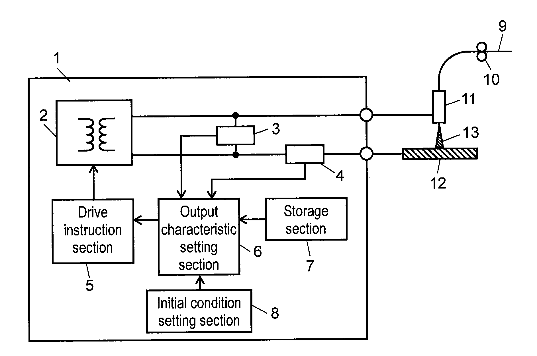
[0019]Hereinafter, a welding control method of the present invention is described based on an exemplary embodiment with reference to drawings. However, the present invention is not intended to be limited to this exemplary embodiment. FIG. 1 is a schematic configuration diagram showing an example of a welding device to which a welding control method is applied in accordance with one exemplary embodiment of the present invention.

[0020]Welding device 1 shown in FIG. 1 includes storage section 7 that stores output characteristics as numerical formulae; initial condition setting section 8 for setting initial welding conditions, and the like; output characteristic setting section 6 for setting an output characteristic based on output characteristics stored in storage section 7, an output from welding voltage detection section 3, an output from welding current detection section 4, and an output from initial condition setting section 8; and drive instruction section 5 fo...


PUM

PropertyMeasurementUnit
pulse frequencyaaaaaaaaaa
voltageaaaaaaaaaa
welding voltageaaaaaaaaaa

Abstract

A welding control method for a welding device having an output characteristic with a predetermined gradient showing a relation between a welding output voltage and a welding output current. By setting a set target welding voltage that is higher than the set initial welding voltage according to a difference between the set initial welding voltage and the welding output voltage, the welding output voltage is controlled to be the set target welding voltage. Thus, a proper arc length can be achieved early by correcting the change of the arc length due to, for example, motion of the hands of a welding operator.

Description

TECHNICAL FIELD[0001]The present invention relates to a welding control method for arc welding in which an arc is generated between a welding wire as a consumable electrode and a base material as a material to be welded, thereby carrying out welding.BACKGROUND ART[0002]In recent years, in the welding industry, the need for improving productivity of welding work and improving product quality has been increased. In particular, automobile and motorcycle industries, the need for improving production efficiency by producing a larger number of materials to be welded (hereinafter, referred to as a “workpiece”) for a short time than before, reducing production cost per workpiece, and reducing occurrence of defective pieces such as those with lack of weld beads or those with holes so as to improve the yield has been increased. In order to meet such needs, it is extremely important to stabilize the arc length during welding.[0003]However, due to displacement of workpieces or inaccuracy of wor...

Claims


Application Information

Patent Timeline
Patent Type & Authority Applications(United States)
IPC IPC(8): B23K9/10
CPCB23K9/0735B23K9/173B23K9/095B23K9/091
Inventor SATO, KIMIYAMUKAI, YASUSHIKAWAMOTO, ATSUHIRONAKAGAWA, AKIRAKOWA, MASARU
Owner PANASONIC CORP
Why Eureka
Try Eureka