Optical element, polarization filter, optical isolator, and optical apparatus

Inactive Publication Date: 2012-01-05
RICOH KK
5 Cites 5 Cited by

AI-Extracted Technical Summary

Problems solved by technology

The materials used in the polarizer discussed in Patent Document 1 are expensive, and its manufacture requires various processing steps including cutting and optical polishing, which tend to make it difficult to reduce manufacturing cost as well as the cost of the optical isolator itself.
In fact, more than half of the manufacturing cost of a conventional optical isol...

Method used

[0047]Generally, a polarization filter is desired to have a high extinction ratio. While the first and the second polarization filters 1 and 2 illustrated in FIG. 1 each have the diffracting structure formed on only one side, this is merely an example. In another embodiment illustrated in FIG. 5, both the first and the second polarization filters 1 and 2 may have the diffracting surfaces (diffracting structures) formed on both sides of each optical element. Such a structure may increase the extinction ratio by the power of two. This is in contrast to Patent Document 1 where the structure employs a birefringent material, where two polarizers are required in order to increase the extinction ratio, resulting in an increase in the thickness of the optical isolator. In accordance with the embodiment of FIG. 5, the extinction ratio can be increased by simply forming the diffracting structures on both sides of the polarization filters 1 and 2.
[0048]Thus, in accordance with the present embodiment, a polarization filter and an optical isolator can be realized using only a surface structure that utilizes diffraction. Thus, the present embodiment enables the mass production of an optical isolator having polarization filters at low cost while maintaining optical characteristics comparable to those of conventional optical isolators. Specifically, the optical isolator 11 according to the present embodiment can be realized without using the conventional birefringent single-crystal prism or the glass containing metal particles, as discussed in Patent Document 1. Further, compared to the photonic crystal system discussed in Patent Document 2, the optical isolator 11 of the present embodiment does not require the formation of a multilayer film comprising a high-refraction index medium and a low-refraction index medium, thus enabling manufacture at low cost.
[0049]Further, because the polarization filter function can be obtained with the surface structure of the polarization filter alone which utilizes diffraction, the need for plural different materials is eliminated. In addition, because the polarization-diffracting function can be exhibited by the diffracting structure alone in which subwavelength concave-convex structures are superposed, the material of the polarization filter can be selected as desired. For example, the diffracting structure may be formed on a substrate material having a high transmittance, or the substrate surface may be coated with a different material on which the diffracting structure may then be formed, depending on the wavelength used. For high-power laser applications and the like, the diffracting structure may be formed on the surface of a material having light resistance.
[0052]In the optical isolator according to the embodiment illustrated in FIG. 6,...

Benefits of technology

[0010]In another aspect, the invention provides an optical isolator comprising a polarization direction rotator disposed between a first polarization filter and a second polarization filter. The first and the second polarization filters are configured to transmit incident light having a particular polarization direction mainly by 0-order transmission and configured to diffract incident light having a polarization direction perpendicular to the particular polarization direction. The first and the second polarization filters include a periodic structure having a period equal to or greater than the wavelength of the incident light. The periodic structure includes first and second subwavelength concave-convex structures perpendicularly disposed adjacent to each other in each period of the periodic structure. The first and the second subwavelength concave-convex structures have a period less than the wavelength of the incident light. A filling factor and a groove depth of the first and the second subwavelength concave-convex structures are determined such that the first and the second subwavelength concave-convex structures have the same effective refraction index with respect to the incident light having the particular polarization direction and a phase difference π with respect to the incident light having the polarization direction perpendicular to the particular polariza...

Abstract

An optical element transmits incident light having a particular polarization direction mainly by 0-order transmission and diffracts incident light having a perpendicular polarization direction. The optical element includes a periodic structure having a period equal to or greater than the wavelength of the incident light. The periodic structure includes first and second subwavelength concave-convex structures formed perpendicularly adjacent to each other in each period of the periodic structure. The first and the second subwavelength concave-convex structures have a period less than the wavelength of the incident light. A filling factor and a groove depth of the first and the second subwavelength concave-convex structures are determined such that they have the same effective refraction index with respect to the incident light having the particular polarization direction and a phase difference π with respect to the incident light having the particular polarization direction.

Application Domain

Polarising elementsDiffraction gratings +1

Technology Topic

Fill factorPerpendicular polarization +8

Image

  • Optical element, polarization filter, optical isolator, and optical apparatus
  • Optical element, polarization filter, optical isolator, and optical apparatus
  • Optical element, polarization filter, optical isolator, and optical apparatus

Examples

  • Experimental program(5)

Example

Embodiment 1
(Optical Isolator)
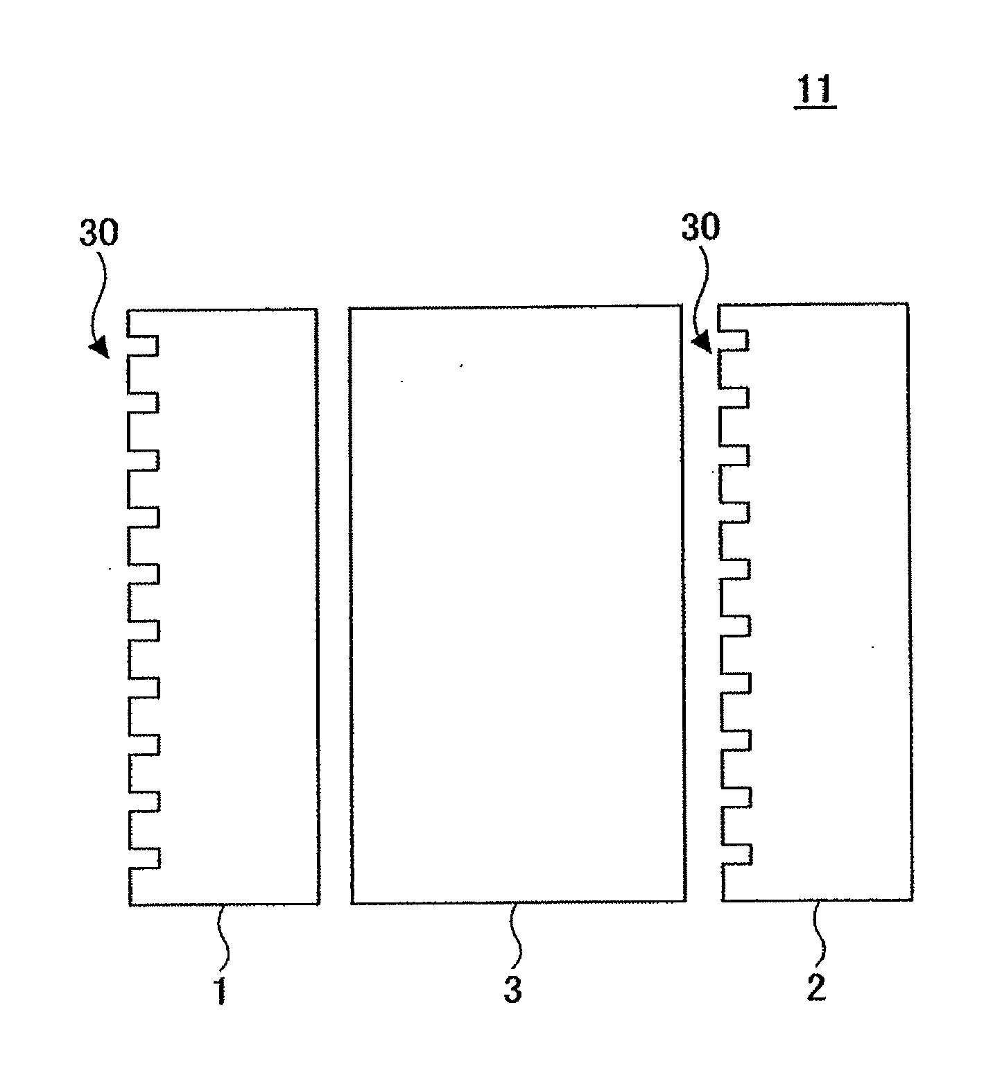
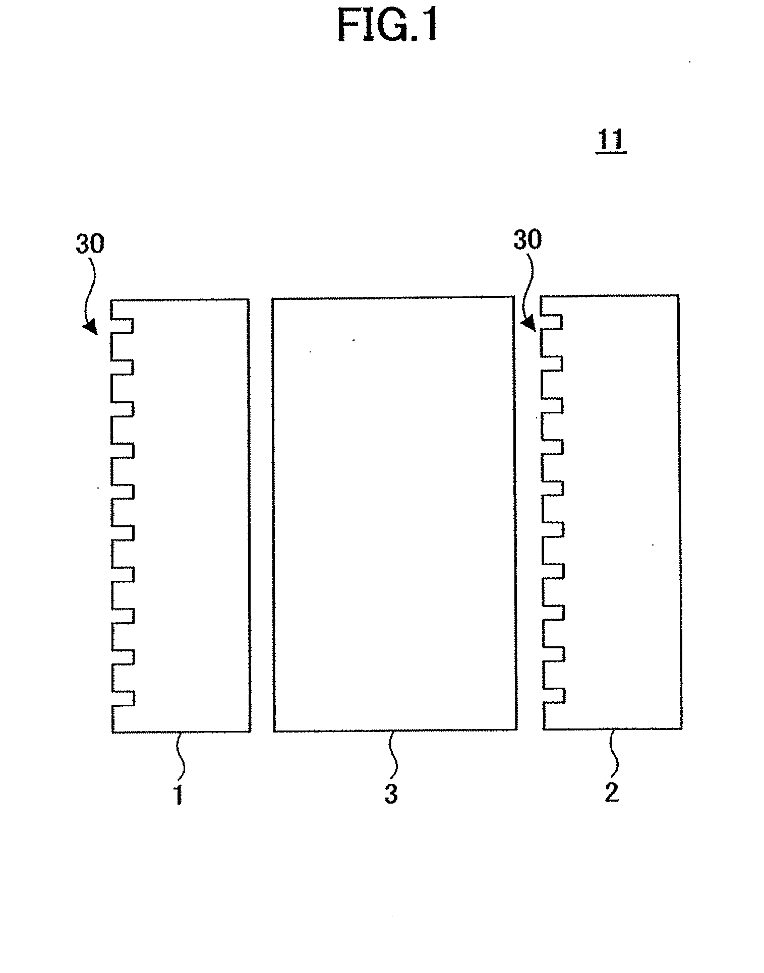
[0037]FIG. 1 is a schematic illustration of an optical isolator 11 according to an embodiment of the present invention. The optical isolator 11 includes a first polarization filter 1, a second polarization filter 2, and a 45° Faraday rotator 3 that are arranged in parallel and fixed to one another, using an adhesive, for example. The first and the second polarization filters 1 and 2 each include a diffracting surface 30 (diffracting structure) on one side. In the following description, for convenience's sake, a polarization direction perpendicular to the plane of the sheet of the drawing may be referred to as a P-polarized direction and a polarization direction within the plane of the sheet of the drawing may be referred to as a S-polarized direction. The first and the second polarization filters 1 and 2 are of a transmitting-diffraction type. The optical isolator 11 is disposed substantially perpendicular to the optical axis of incident light.
[0038]The first and the second polarization filters 1 and 2 are disposed so that their transmitting-polarization directions are at an angle of 45° with each other. The first and the second polarization filters 1 and 2 are diffracting elements having a diffracting structure with periods equal to or more than the wavelength of the incident light. Each period of the diffracting structure includes two patterns of subwavelength concave-convex structures that are disposed perpendicularly adjacent to each other, the two different patterns having periods less than the wavelength of the incident light. As will be described later with reference to Embodiment 4, a filling factor and a groove depth of the two patterns of subwavelength concave-convex structures are determined such that the two patterns have the same effective refraction index with respect to the incident light of S-polarized direction and a phase difference π with respect to the incident light of P-polarized direction.
[0039]The first and the second polarization filters 1 and 2 having large areas may be mass-produced by semiconductor processes, and do not require optical polishing. Details of the manufacturing method will be described with reference to Embodiment 5. The 45° Faraday rotator 3 may include a GdBiFe garnet thick film, to which a magnetic field is applied by a magnetic field applying unit (not shown) which may include a permanent magnet or an electromagnet in a direction along the propagation of light.
(Optical Apparatus)
[0040]FIG. 2 is a schematic illustration of an optical apparatus 200 including the optical isolator 11 illustrated in FIG. 1. The optical apparatus 200 includes a laser diode 9 configured to emit a laser beam that is shaped into a substantially parallel beam via a first lens 10. The parallel beam is incident on the optical isolator 11, and transmission light that has passed through the optical isolator 11 is focused by a second lens 21 at an end of an optical fiber 12. The laser diode 9, the first lens 10, the optical isolator 11, the second lens 21, and the optical fiber 12 are aligned with an optical axis 0 of the laser beam of light. The optical apparatus 200 may be used in an optical communication apparatus for optical fiber communications or in an optical information processing apparatus.
(Optical Path of Optical Isolator)
[0041]In FIGS. 1 and 2, the incident light is incident on the first polarization filter 1 of the optical isolator 11 and then has its P-polarized component diffracted by a first surface (where the diffracting structure is formed) of the first polarization filter 1. Most of the S-polarized component of the incident light is transmitted by 0-order transmission (dead-zone transmission). The 0-order-transmitted S-polarized component is perpendicularly incident on the 45° Faraday rotator 3, by which the polarization direction of the S-polarized component is rotated +45° and caused to emerge towards the second polarization filter 2 on the emerging side without being attenuated. Then, as in the case of the first polarization filter 1, the second polarization filter 2 diffracts the light of a polarization direction that is not to be used while allowing the transmission of the light of a polarization direction that is to be incident on the end of the optical fiber 12 by dead-zone transmission.
[0042]With regard to backward direction light, although the polarized component that has been transmitted through the second polarization filter 2 by 0-order transmission may have its polarization rotated by −45° by the nonreciprocal action of the Faraday rotator 3 and then become incident on the first polarization filter 1, such light is diffracted because it is perpendicular to the polarization direction of the incident light from the light source that is transmitted by 0-order transmission.
[0043]The first and the second polarization filters 1 and 2 are configured such that the light diffracted by each has a sufficient angle with the 0-order transmission light, so that the forward direction light can be prevented from becoming incident on the end of the optical fiber 12, and so that the backward direction light can be prevented from becoming incident on the laser diode 9. For example, the pitch of the diffracting structures is set so that the ±1st-order diffracted light has an angle of 10° or more.
(Structure of Polarization Filter)
[0044]The first polarization filter 1 is configured to diffract the P-polarized component while allowing the S-polarized component to be transmitted without diffracting it. With reference to FIGS. 3A and 3B, a macroscopic structure of the first polarization filter 1 is described. FIG. 3A is a schematic front view of the first polarization filter 1. FIG. 3B is a schematic cross section of the first polarization filter 1. The first polarization filter 1 includes a lattice-shaped diffracting surface (diffracting structure) configured to diffract the P-polarized component of light while allowing the S-polarized component of light to pass without diffracting it.
[0045]FIG. 4A is an enlarged perspective view of a main portion of the lattice formed on the diffracting surface of the first polarization filter 1 illustrated in FIGS. 3A and 3B. The enlarged view of FIG. 4A shows the lattice corresponding to three of the periods P each of which is equal to or greater than the wavelength of the incident light. As illustrated in FIG. 4A, the periodic structure of the lattice having the periods P includes subwavelength concave-convex structures 400 and 401. As illustrated in FIGS. 4B and 4C, the subwavelength concave-convex structures 400 and 401 have periods q1 and q2, respectively, which are shorter than the wavelength. The incident light is diffracted by the periodic structure whose periods correspond to the wavelength of the incident light or longer, and the subwavelength concave-convex structures 400 and 401 provide polarization selectivity in determining whether the P-polarized component or the S-polarized component of the light is diffracted. Thus, as illustrated in FIG. 3B, the first polarization filter 1 diffracts the P-polarized component and passes the S-polarized component by dead-zone transmission.
(Extinction Ratio)
[0046]Generally, an extinction ratio may be used when specifying a reflecting-type polarizer used in an optical isolator. The extinction ratio indicates the ratio of the transmittance of the S-polarized light, which may be the polarization direction to be used, to the transmittance of the P-polarized light, which may be the polarization direction not to be used. In accordance with the present embodiment of the present invention, the extinction ratio is expressed as the ratio of the diffraction efficiency of the 0-order light in the S-polarization direction to the diffraction efficiency of the 0-order light in the P-polarized direction.
[0047]Generally, a polarization filter is desired to have a high extinction ratio. While the first and the second polarization filters 1 and 2 illustrated in FIG. 1 each have the diffracting structure formed on only one side, this is merely an example. In another embodiment illustrated in FIG. 5, both the first and the second polarization filters 1 and 2 may have the diffracting surfaces (diffracting structures) formed on both sides of each optical element. Such a structure may increase the extinction ratio by the power of two. This is in contrast to Patent Document 1 where the structure employs a birefringent material, where two polarizers are required in order to increase the extinction ratio, resulting in an increase in the thickness of the optical isolator. In accordance with the embodiment of FIG. 5, the extinction ratio can be increased by simply forming the diffracting structures on both sides of the polarization filters 1 and 2.
[0048]Thus, in accordance with the present embodiment, a polarization filter and an optical isolator can be realized using only a surface structure that utilizes diffraction. Thus, the present embodiment enables the mass production of an optical isolator having polarization filters at low cost while maintaining optical characteristics comparable to those of conventional optical isolators. Specifically, the optical isolator 11 according to the present embodiment can be realized without using the conventional birefringent single-crystal prism or the glass containing metal particles, as discussed in Patent Document 1. Further, compared to the photonic crystal system discussed in Patent Document 2, the optical isolator 11 of the present embodiment does not require the formation of a multilayer film comprising a high-refraction index medium and a low-refraction index medium, thus enabling manufacture at low cost.
[0049]Further, because the polarization filter function can be obtained with the surface structure of the polarization filter alone which utilizes diffraction, the need for plural different materials is eliminated. In addition, because the polarization-diffracting function can be exhibited by the diffracting structure alone in which subwavelength concave-convex structures are superposed, the material of the polarization filter can be selected as desired. For example, the diffracting structure may be formed on a substrate material having a high transmittance, or the substrate surface may be coated with a different material on which the diffracting structure may then be formed, depending on the wavelength used. For high-power laser applications and the like, the diffracting structure may be formed on the surface of a material having light resistance.
[0050]Because such a method of manufacturing the optical element (polarization filter) according to the present embodiment does not require optical polishing of large areas, the optical element can be mass-produced at low cost without adversely affecting optical characteristics. Further, because the light in an undesired polarization direction is diffracted, the optical isolator does not need to be disposed at an angle, thus making it possible to realize a layout in which a light beam can be substantially perpendicularly incident on the optical isolator.

Example

Embodiment 2
(Optical Isolator)
[0051]Next, an optical isolator according to another embodiment of the present invention is described. Because the polarization filter function can be realized by the diffracting structure alone formed on an optical element, an optical isolator structure illustrated in FIG. 6 may be employed. Specifically, a diffracting surface (diffracting structure) 31 having the function of the first polarization filter 1 may be formed on a surface on the incident side of the Faraday rotator 3, and a diffracting surface (diffracting structure) 32 having the function of the second polarization filter 2 may be formed on a surface on the emerging side of the Faraday rotator 3. The diffracting structures 31 and 32 may be directly formed on the surfaces of the Faraday rotator 3, or the surfaces of the Faraday rotator 3 may be initially coated with a separate material, and then the diffracting structures 31 and 32 may be formed on the coated surfaces. Thus, in accordance with the present embodiment illustrated in FIG. 6, an optical isolator function can be provided by the single optical element.
[0052]In the optical isolator according to the embodiment illustrated in FIG. 6, because the polarization filters and the Faraday rotator are integrated, the optical isolator 11 can be handled more easily and made smaller in size as an optical system than the structure comprising a Faraday rotator disposed between polarizers. Further, because the polarization-diffracting function can be provided by the diffracting structure alone in which subwavelength concave-convex structures are superposed, the material of the optical isolator can be selected as desired. Thus, as illustrated in FIG. 6, the diffracting structures 31 and 32 may be directly formed on the Faraday rotator 3, or the surface of the Faraday rotator 3 may be coated with a material and then the diffracting structures 31 and 32 may be formed on the coated surfaces.

Example

Embodiment 3
[0053]FIG. 7 illustrates an optical isolator 11 in which the structures according to Embodiments 1 and 2 are combined. The optical isolator 11 illustrated in FIG. 7 includes a Faraday rotator 3 on both sides of which the diffracting structures 702 including the subwavelength concave-convex structures are formed after coating the sides with a separate material. The first and the second polarization filters 1 and 2 including the corresponding subwavelength concave-convex structures 701 formed on corresponding substrates 704 are then disposed opposite the corresponding diffracting structures 702. Gap retainers 703 may be provided between the opposing diffracting structures 701 and 702 in order to maintain predetermined gaps between them.
[0054]While the diffracting structures 701 of the first and the second polarization filters 1 and 2 may not be disposed facing each other, doing so prevents the exposure of the diffracting structures 701 to the outside, thereby preventing the diffracting structures 701 from being damaged or influenced by dust and the like. Further, the external surface may be polished to reduce the thickness of the optical isolator 11 or adjust its optical path length.
[0055]While the optical isolator 11 according to Embodiments 1 and 2 employs the Faraday rotator 3, the Faraday rotator 3 may be replaced with a polarization rotating element such as a wavelength plate. In this case, the need for application of a magnetic field may be eliminated, so that the structure of the optical isolator 11 may be simplified. Such a wavelength plate may include a birefringent material such as a crystal, or the subwavelength concave-convex structure used in the polarization filter 1 or 2 of the foregoing embodiments. Alternatively, the polarization filter may be provided on the front side alone of the Faraday rotator, in which case a further decrease in thickness or cost may be achieved, although the extinction ratio may decrease.

PUM

no PUM

Description & Claims & Application Information

We can also present the details of the Description, Claims and Application information to help users get a comprehensive understanding of the technical details of the patent, such as background art, summary of invention, brief description of drawings, description of embodiments, and other original content. On the other hand, users can also determine the specific scope of protection of the technology through the list of claims; as well as understand the changes in the life cycle of the technology with the presentation of the patent timeline. Login to view more.
Why Eureka
Try Eureka