
Two stage hydroprocessing with divided wall column fractionator

a fractionator and divided wall technology, applied in the direction of hydrocarbon oil treatment products, separation processes, fuels, etc., can solve the problems of no description or suggestion of any interaction, recycling or other mixing of the gasoline “bottoms” portions, and the need for equipment, so as to improve the cold flow property and reduce the amount of sulfur. , the effect of low sulfur

Inactive Publication Date: 2012-01-05
EXXON RES & ENG CO
View PDF0 Cites 53 Cited by
  • Summary
  • Abstract
  • Description
  • Claims
  • Application Information

AI Technical Summary

Benefits of technology

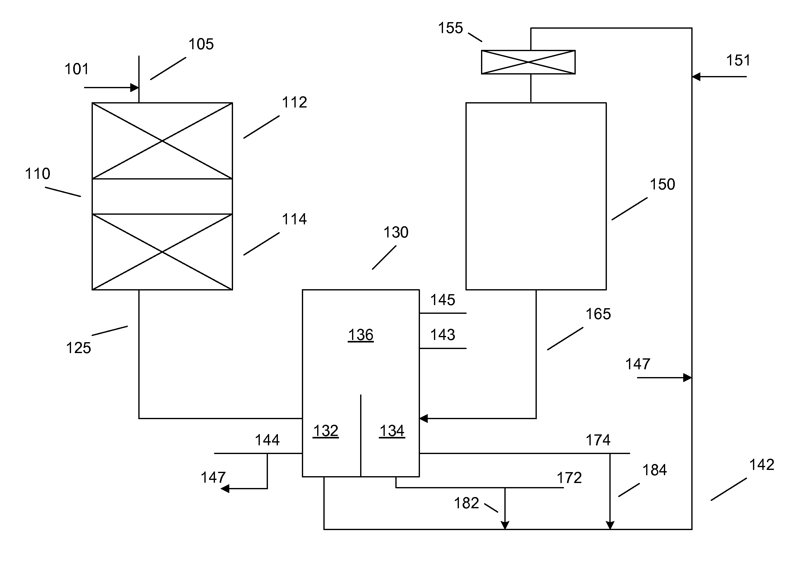
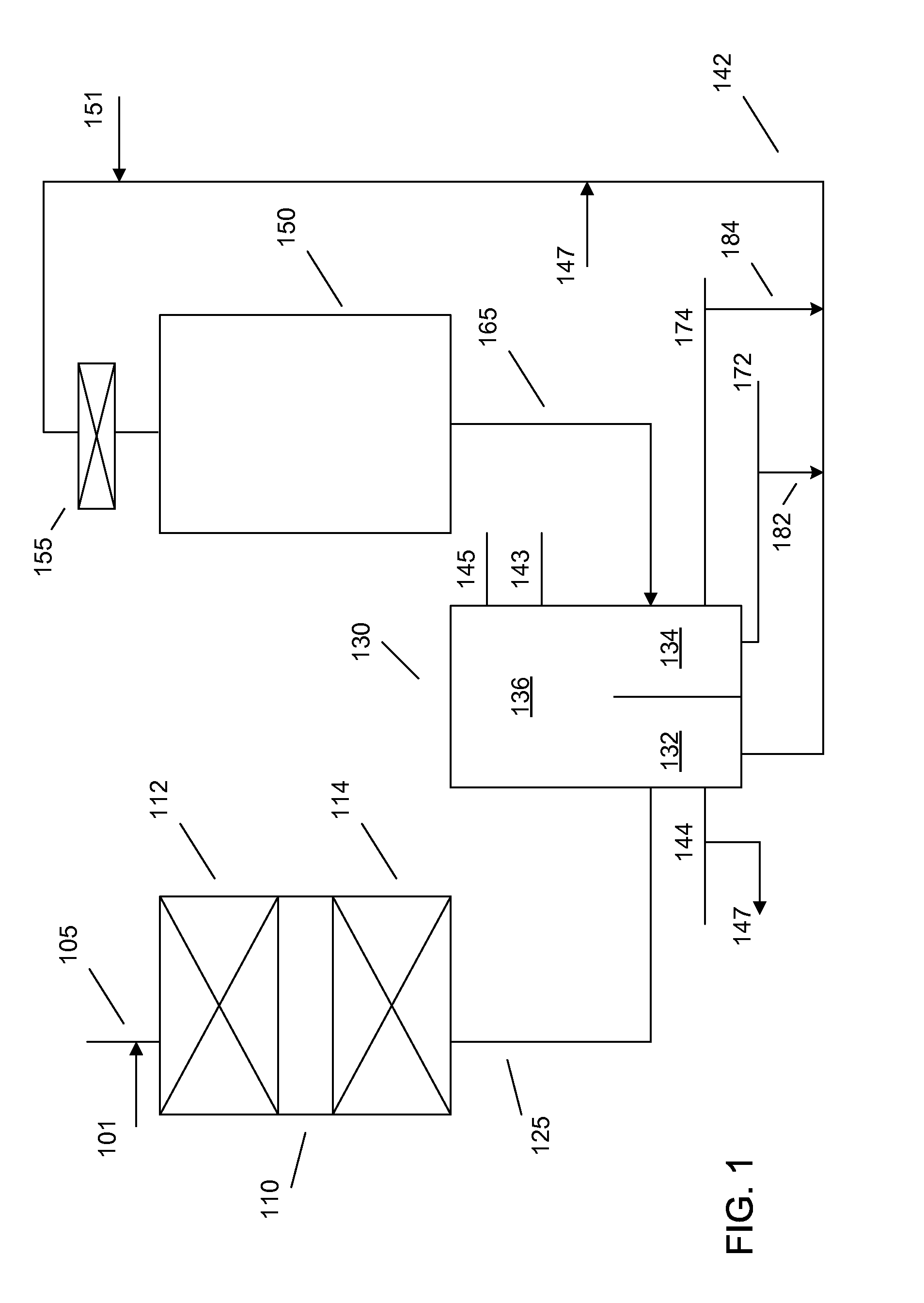
[0012]This invention provides various systems and methods for improved processing of hydrocarbon feeds. In various embodiments, the advantages of the systems and methods can include, but are not limited to, reduced equipment needs and / or reduced cost production of multiple distillate product streams from multiple reactor systems.

Problems solved by technology

The equipment necessary for refining operations is one of the major sources of costs in a refinery.
However, there is no description or suggestion of any interaction, recycling, or other mixing of the gasoline “bottoms” portions.

Method used


Image

  • Two stage hydroprocessing with divided wall column fractionator
  • Two stage hydroprocessing with divided wall column fractionator
  • Two stage hydroprocessing with divided wall column fractionator

Examples


embodiment 1

[0077]A method for producing low sulfur distillate products, comprising: hydrotreating a feedstock under first effective hydrotreating conditions; fractionating the hydrotreated feedstock in a first volume of a divided wall column fractionator to produce at least a first product fraction, a first bottoms fraction, and a first common fraction that is passed to an upper undivided volume of the fractionator; dissolving hydrogen in at least a portion of the first bottoms fraction to approximately the solubility limit; hydrocracking the portion of the first bottoms fraction under effective hydrocracking conditions in a hydrocracking stage having a continuous liquid environment; and fractionating the hydrocracked first bottoms fraction in a second volume of the divided wall column fractionator to produce at least a second product fraction, a third product fraction, and a second common fraction that is passed to the upper undivided volume of the fractionator, wherein the second product fra...

embodiment 2

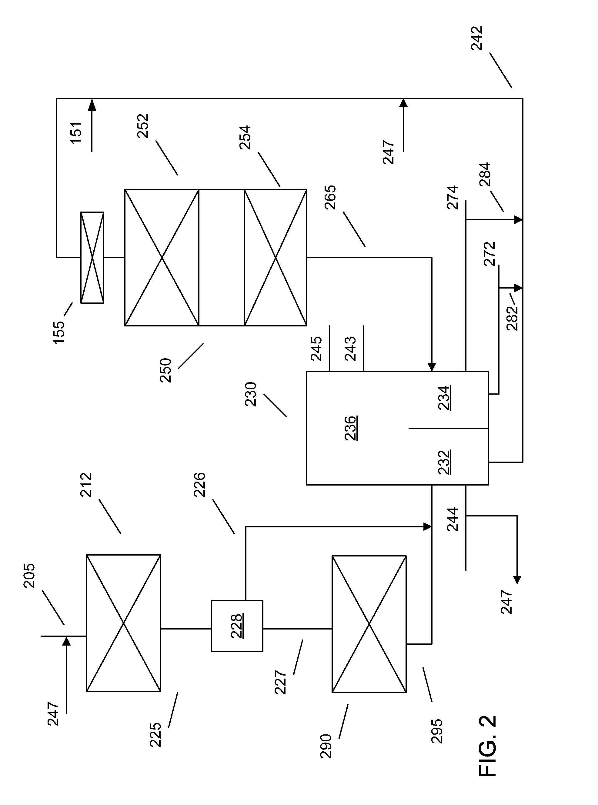
[0078]A method for producing low sulfur distillate products, comprising: hydrotreating a feedstock under effective hydrotreating conditions; hydrocracking the hydrotreated feedstock in a first hydrocracking stage under first effective hydrocracking conditions; fractionating the hydrocracked feedstock in a first volume of a divided wall column fractionator to produce at least a first diesel product fraction and a first bottoms fraction; hydrocracking a portion of the bottoms fraction in a second hydrocracking stage having a continuous liquid environment under second effective hydrocracking conditions; dewaxing the hydrocracked portion of the first bottoms fraction in a dewaxing stage having a continuous liquid environment under effective dewaxing conditions; and fractionating the hydrocracked, dewaxed bottoms fraction in a second volume of the divided wall column fractionator to produce at least a second diesel product fraction and a second bottoms fraction, wherein the second diesel...

embodiment 3

[0079]The method of embodiment 1, further comprising hydrocracking the hydrotreated feed under effective hydrocracking conditions in a continuous gas phase environment prior to passing the hydrotreated feed to the first volume of the divided wall column.


PUM


Abstract

A divided wall column can allow for fractionation of multiple streams while maintaining separate product qualities. Effluents from multiple stages of a reaction system can be processed in a single divided wall column. The divided wall column can produce multiple cuts from each separated area, as well as at least one output from a common area. At least one reaction stage can advantageously have a continuous liquid phase environment.

Description

CROSS-REFERENCE TO RELATED APPLICATIONS[0001]This application claims the benefit of U.S. Application No. 61 / 359,883, filed Jun. 30, 2010, the entire contents of which are hereby incorporated by reference herein.FIELD OF THE INVENTION[0002]This invention provides methods for multi-stage hydroprocessing using a divided wall column as a fractionator.BACKGROUND OF THE INVENTION[0003]The equipment necessary for refining operations is one of the major sources of costs in a refinery. The equipment can include catalytic reactors, fractionators and / or separators, and other supporting equipment. In a conventional process train, each catalytic reactor can have a dedicated fractionator or separator associated with the reactor, to separate out the various products produced in the catalytic reaction stage.[0004]One method for saving on capital costs is to allow more than one reactor to use the same fractionator. U.S. Pat. No. 3,412,016 shows an example of a fractionator that includes multiple vol...

Claims


Application Information

Patent Timeline
IPC IPC(8): C10G3/00C07C7/00C07C4/00C10G69/02C10G65/12
CPCB01D3/141B01D3/143C10G65/12C10L1/08C10G2300/202C10G2300/304C10G2400/04C10G2300/1011C10G2300/1055C10G2300/301C10G2300/4006C10G2300/4012C10G2300/4018Y02P30/20
Inventor UMANSKY, BENJAMIN S.DOUGHERTY, RICHARD C.HAYES, MICHAEL A.LEWIS, WILLIAM E.
Owner EXXON RES & ENG CO
Learn More