Strength-increasing shield tunneling machine cutter ring machining process

A technology of increasing strength and processing technology, which is applied in the field of shield machine cutter ring processing technology for increasing strength, can solve problems such as easy deformation, and achieve the effects of increasing pressure, reducing contact area, and facilitating stamping and forming

Inactive Publication Date: 2019-05-10
JIASHAN XINQIANG STEEL IND CO LTD
View PDF6 Cites 13 Cited by
  • Summary
  • Abstract
  • Description
  • Claims
  • Application Information

AI Technical Summary

Problems solved by technology

[0004] The above-mentioned existing technical solutions have the following defects: during the tool processing process, the tool is not only subjected to friction force, but also has a relatively large pressure force, which is prone to deformation

Method used


Image

  • Strength-increasing shield tunneling machine cutter ring machining process
  • Strength-increasing shield tunneling machine cutter ring machining process
  • Strength-increasing shield tunneling machine cutter ring machining process

Examples


Embodiment 1

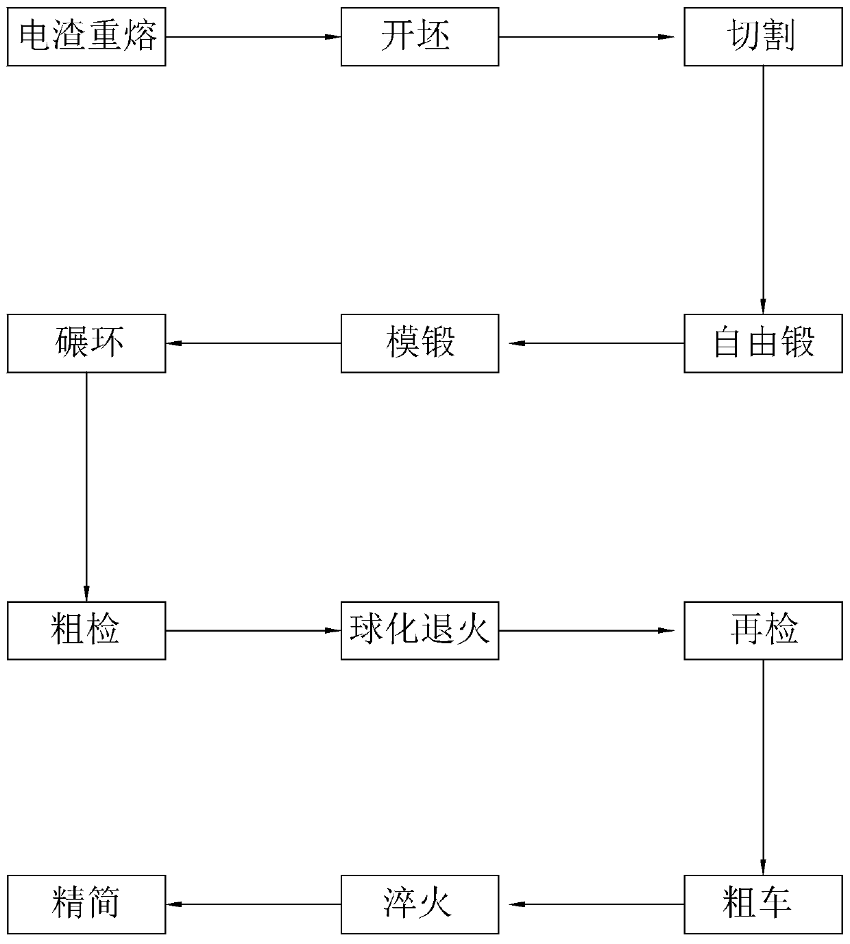
[0035] Embodiment 1: A kind of shield machine cutter ring processing technology that increases strength, such as figure 1 shown, including the following steps:

[0036] Step S1: electroslag remelting, placing the steel ingot in an electroslag furnace for remelting, so that the electroslag is remelted into an electroslag ingot. The electroslag remelted steel has high purity, low sulfur content, less non-metallic inclusions, smooth surface of steel ingot, clean uniform and dense, uniform metallographic structure and chemical composition, so the material structure strength is higher.

[0037] Step S2: billet opening, forging the electroslag ingot with an electro-hydraulic hammer, heating the electroslag ingot to above 800°C before billet opening, and shaping it into a cylindrical bar under the impact of the electro-hydraulic hammer.

[0038] Step S3: Cutting, first annealing the original bar, using annealing to release the internal stress generated by blank forging, and reduce t...

Embodiment 2

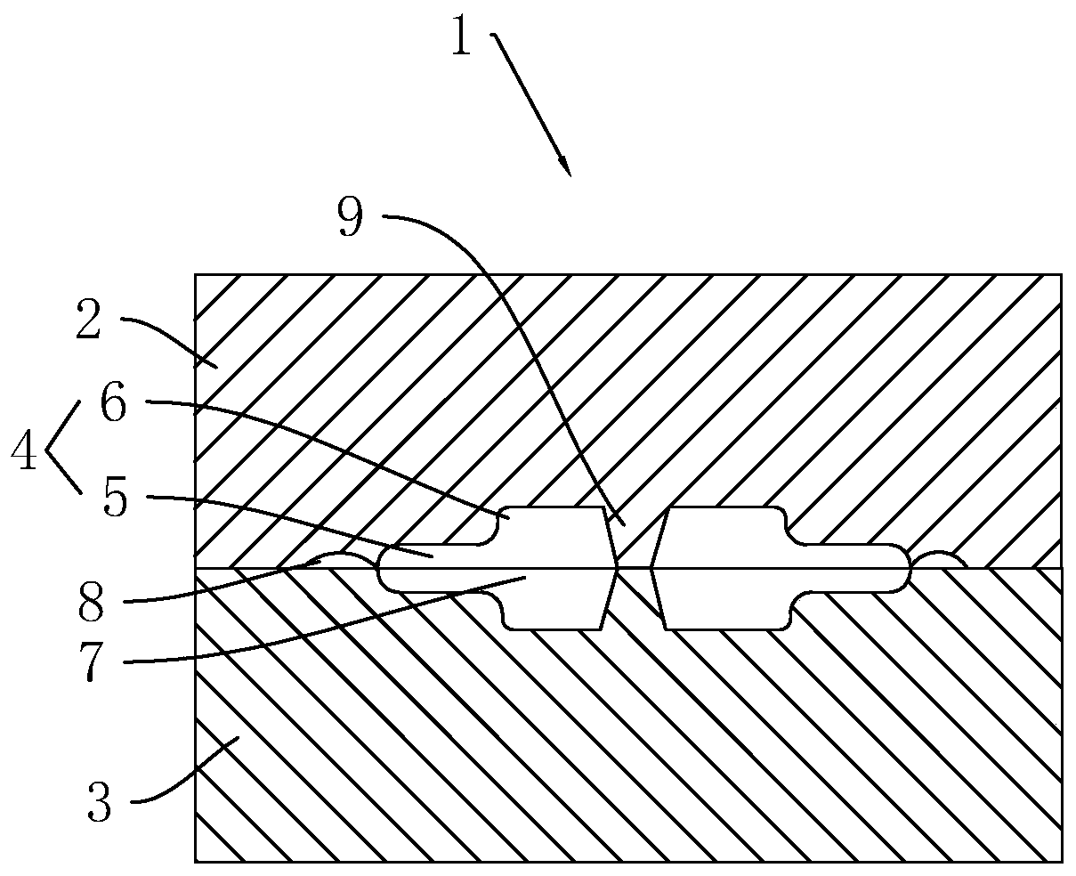
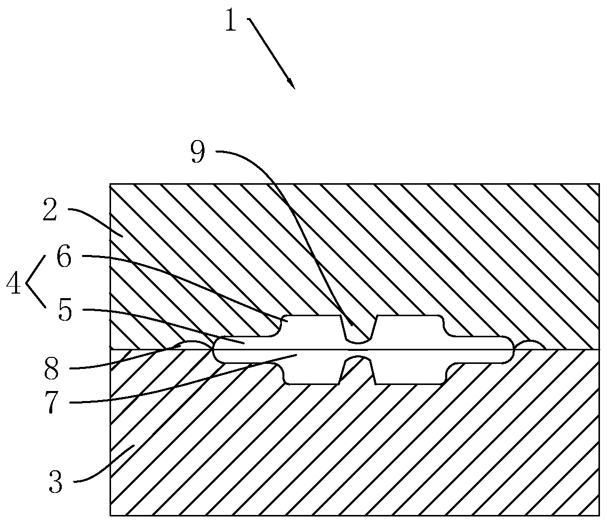
[0049] Embodiment 2: A kind of shield machine cutter ring processing technology that increases strength, such as image 3 As shown, the difference from Example 1 is that step S5: die forging, the rough blank after free forging is placed in the forging die 1, and the temperature of the rough blank is not cooled at this time, and the rough blank is forged and formed into The rough-formed billet has a central groove formed by forging and pressing at the center of the rough-formed billet, and the thickness of the outer ring is smaller than that near the center.

[0050] The die forging machine is a steam-air hammer. The forging die 1 includes an upper die 2 and a lower die 3 . A circular forging die groove 4 is provided on the lower surface of the upper die 2 and the upper surface of the lower die 3 . The forging die groove 4 includes a first ring groove 5 and a second ring groove 6, the first ring groove 5 and the second ring groove 6 are arranged coaxially and communicate with e...


PUM


Abstract

The invention discloses a strength-increasing shield tunneling machine cutter ring machining process, and belongs to the field of shield tunneling machine cutters. According to the technical scheme, the machining process comprises the following steps of S1 electro-slag remelting, S2 cogging, S3 cutting, S4 free forging, S5 die forging, S6 ring grinding, S7 rough inspecting, S8 spheroidizing annealing, S9 secondary inspecting, S10 rough turning, S11 quenching and S12 fine inspecting, wherein in the first step, an electro-slag furnace is utilized for remelting steel ingots into ESR ingots; in the second step, an electro hydraulic hammer is utilized for forging the ESR ingots into raw rod materials; in the fourth step, rod material blanks are subjected to free forging to upsetting; and in thetwelfth step, a cutter ring is cooled, and then the outer diameter, the inner diameter, the inner ring thickness and the outer ring thickness of the cutter ring are inspected. The strength-increasingshield tunneling machine cutter ring machining process has the effect of strengthening the cutter structure.

Description

technical field [0001] The invention relates to the technical field of shield machine cutters, more specifically, it relates to a process for processing shield machine cutter rings with increased strength. Background technique [0002] Shield cutting tools are mainly used for shield tunneling in subways and tunnels. Its structure is to weld one or more rows of cylindrical alloys in front of the cutter body. When the shield tool rotates with the cutter head in the circumferential direction, it starts to cut. When it encounters sand and pebbles, it is easy to cause the tool body to wear too fast and the alloy to crack. After the back angle surface of the body is severely worn, the main alloy is impacted and the tool is scrapped. Therefore, it is necessary to improve the wear resistance of the shield cutter. By improving the structural performance of the shield cutter, the wear resistance of the shield cutter can be improved, and the wear degree of the shield cutter during the...

Claims


Application Information

Patent Timeline
Patent Type & Authority Applications(China)
IPC IPC(8): B23P15/28
Inventor 陈叙超
Owner JIASHAN XINQIANG STEEL IND CO LTD
Why Eureka
Try Eureka