Device for detection and determination of the composition of bulk material

a bulk material and composition technology, applied in the field of agricultural and harvesting crop processing, can solve the problems of grain loss, interference with the further processing, and large portion of damaged grain, and achieve the effect of improving the detection of crop material flow

Active Publication Date: 2012-01-05
CLAAS SELBSTFAHRENDE ERNTEMASCHINEN GMBH
View PDF7 Cites 43 Cited by
  • Summary
  • Abstract
  • Description
  • Claims
  • Application Information

AI Technical Summary

Benefits of technology

[0010]The problem addressed by the invention is therefore that of creating a device for the detection and determination of the composition of bulk material, in particular crop material in grain tanks of agricultural harvesting machines of the initially stated type, which prevents the stated disadvantages of the devices known from the prior art, and of providing a technical solution that enables improved detection of the crop material flow to determine the quality of the crop material.

Problems solved by technology

However, not all of the grains are threshed out entirely from the ears of the crop material in the threshing process, and so a combine harvester comprises—in a known manner—a forward grain path and a return path, i.e. a mechanical return path, via which incompletely threshed ears are returned to the threshing process to be threshed again.
If the setting for the threshing mechanism is too acute, the portion of damaged grain becomes too great, which is undesirable.
If the setting is too gentle, grains that have not been fully threshed enter the crop material, which interferes with the further processing thereof.
Husks and short straw that enter the crop material flow during threshing may be removed in a separating unit located downstream of the threshing stage, although a setting of the separating unit that is too acute may also result in grain losses.
However, one disadvantage thereof is that grain, damaged grain, and non-grain components, and fine dust separate into different layers at the point of image measurement, or have already become separated.
Since some components of the crop material flow are lighter-weight and others are heavier, the crop material flow separates into different layers, the detection of which by the image recording unit does not allow the quality of the components of the crop material to be assessed with sufficient accuracy, because all layers are not detected in a homogeneous manner.

Method used


Image

  • Device for detection and determination of the composition of bulk material
  • Device for detection and determination of the composition of bulk material
  • Device for detection and determination of the composition of bulk material

Examples


first embodiment

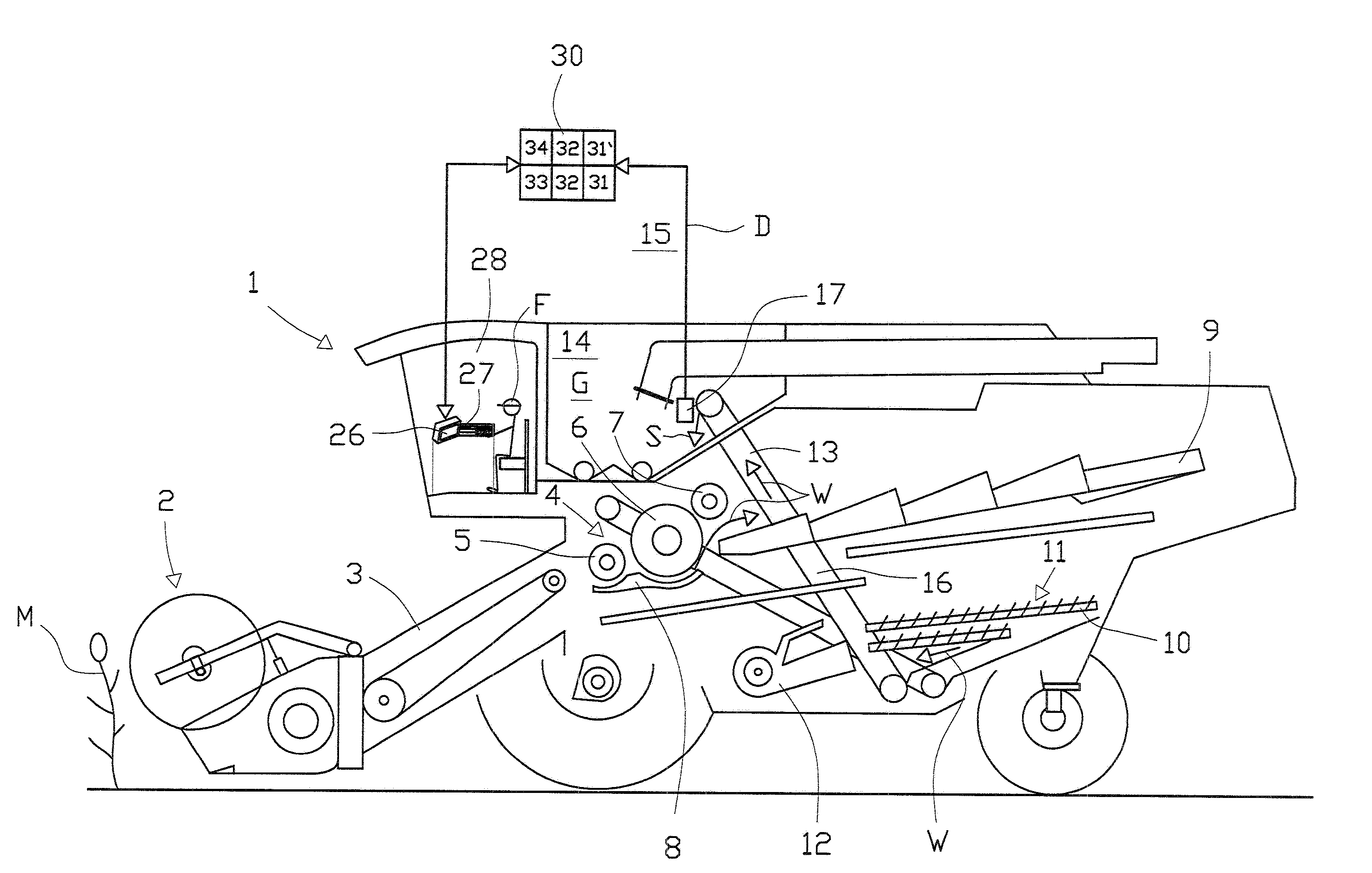
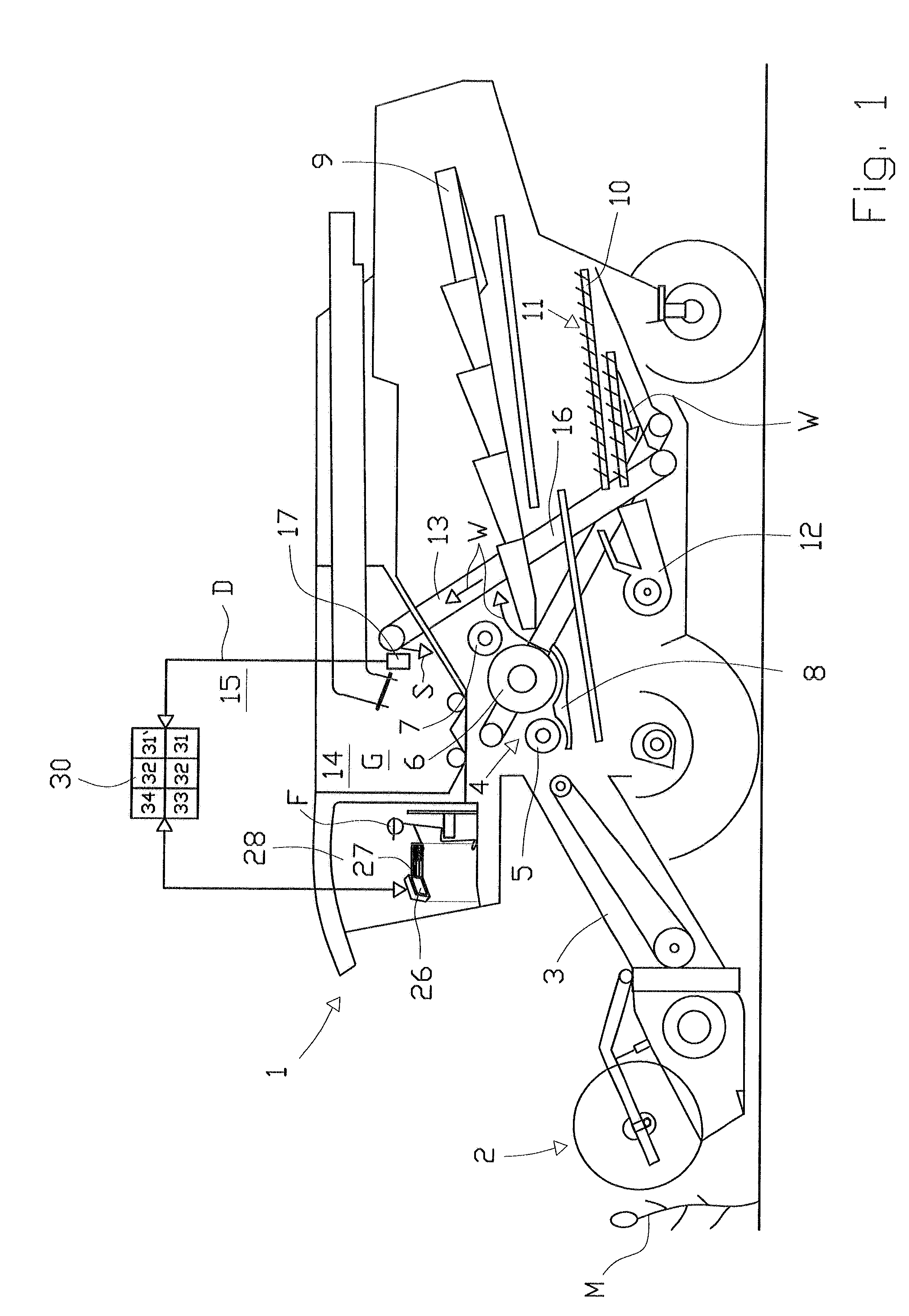
[0034]As shown in FIG. 1, control unit 30 is connected via a data line D to image recording unit 17 according to the invention. Image recording unit 17 can have various technical embodiments. It can comprise two to four stationary image detectors 18, 20 or one or more movably disposed image detectors 18, 20. The principle is to use imaging detectors to detect, with the aid of an optical recording, the separation of crop material flow S in a grain elevator 13 before transfer thereof into a container 14 in order to determine crop material quality. The detection and evaluation method is the same in all three technical embodiments of device 15. Of the three technical embodiments of image recording units 17, an image recording unit 17 comprising two stationary image detectors 18, 20 is depicted preferably in FIG. 2. Image detectors 18, 20 are diametrically opposed at the outlet of an elevator head 41, i.e. discharge point 40, and are therefore separated by 180 degrees. Image detectors 18...

second embodiment

[0035]In a development (not depicted in FIG. 2) of optimal image recording unit 17, one more image detector is located on both sides of discharge point 40. Using the total of four image detectors 18, 20, it is now possible to detect crop material flow S from all sides, each image detector 18, 20 being disposed approximately perpendicularly to surface 23 of crop material flow S. This technical embodiment of an image recording unit 17 corresponds to the second embodiment described above.

[0036]The opening of the angular field of each image detector 18, 20 forms a field of view 42, 43. A yield sensor in the form of a baffle plate 44 and a weight sensor 45 assigned thereto is located within said field of view 42, 43, at outlet 40 of elevator head 41, and can function as an alternative to the yield sensor designed as light barrier 16. Image detectors 18, 20 detect the fill level of crop G in the region of elevator head 41, which is evaluated in control unit 30 using image processing. The ...

third embodiment

[0043]In device 15 described above, it is provided according to the invention for at least one and preferably both stationary image detectors 18, 20 to be movable. This embodiment is not depicted in entirety in FIG. 2. To this end, housing part 19, 21 containing image detector 18, 20 is displaceably disposed at discharge point 40. To displace housing part 19, 21, housing part 19, 21 is connected via a connecting means to a drive unit which is not depicted. Discharge point 40 comprises a longitudinal slot through which the image or image series can be recorded.

[0044]It will be understood that each of the elements described above, or two or more together, may also find a useful application in other types of constructions differing from the types described above.

[0045]While the invention has been illustrated and described as embodied in a device for detection and determination of the composition of bulk material, it is not intended to be limited to the details shown, since various modi...


PUM


Abstract

A device for detection and determination of a composition of a bulk material, has an image recording unit, at least one control unit, at least one memory unit, and a selection unit to enable a qualified determination to be made, during a transfer of a crop material flow into a container of an agricultural harvesting machine, of a composition of a crop during processing of the crop material, so that adjustment parameters of working assemblies of the agricultural harvesting machine are changeable during the processing of the crop material, wherein the image recording unit has at least two image detectors for recording images or image series of the crop material flow at equidistant intervals or permanently, wherein one of the image detectors is disposed substantially perpendicularly to a top side of a surface of the crop material flow emerging from a grain elevator head or a discharge chute, and another one of the two image detectors is disposed substantially perpendicularly to an underside of a surface of the crop material flow.

Description

CROSS-REFERENCE TO RELATED APPLICATION[0001]The invention described and claimed hereinbelow is also described in German Patent Application DE 10 2010 017 688.5 filed on Jul. 1, 2010. This German Patent Application, whose subject matter is incorporated here by reference, provides the basis for a claim of priority of invention under 35 U.S.C. 119(a)-(d).BACKGROUND OF THE INVENTION[0002]The present invention relates in general to the field of agriculture and the processing of harvested crops.[0003]Vehicles designed to pick up and process crops—in particular self-propelled agricultural harvesting machines—are used for this purpose. The self-propelled agricultural harvesting machines are typically combine harvesters, forage harvesters, and all types of lifters that are operated to cut and / or gather crop material. Such machines typically can process the crop material in a known manner after cutting and / or gathering. One example will be described with reference to a combine harvester. In a...

Claims


Application Information

Patent Timeline
Patent Type & Authority Applications(United States)
IPC IPC(8): A01D41/127G06F19/00
CPCA01D41/127A01D41/1277
Inventor BEHNKE, WILLI
Owner CLAAS SELBSTFAHRENDE ERNTEMASCHINEN GMBH
Why Eureka
Try Eureka