
Semiconductor light-emitting device and method of manufacturing the same

a technology of semiconductors and light-emitting devices, which is applied in the direction of semiconductor/solid-state device manufacturing, semiconductor devices, electrical devices, etc., can solve the problems of short circuit of wires and limited light extraction, so as to prevent the light-emitting area from being reduced

Active Publication Date: 2012-01-12
SAMSUNG ELECTRONICS CO LTD
View PDF1 Cites 66 Cited by
  • Summary
  • Abstract
  • Description
  • Claims
  • Application Information

AI Technical Summary

Benefits of technology

The present invention provides semiconductor light-emitting devices that prevent a reduction in light-emitting area by disposing a p-type electrode and an n-type electrode under a semiconductor structure and without the need for wire bonding. The devices include a first electrode layer, an insulating layer, a second electrode layer, a second semiconductor layer, an active layer, and a first insulating layer. A first contact passes through the substrate to be electrically connected to the first electrode layer, and a second contact passes through the substrate to be electrically connected to the second electrode layer. The first electrode layer is filled in a contact hole that passes through the second semiconductor layer, the active layer, and the insulating layer to be connected to the first semiconductor layer. The method of manufacturing the semiconductor light-emitting device includes sequentially forming layers on a substrate, forming a contact hole, and forming insulating layers and electrodes to connect to the contact hole. The devices and methods provide improved efficiency and reliability.

Problems solved by technology

Also, since a horizontal light-emitting device requires wire bonding, a wire may be short-circuited due to heat generated in the horizontal light-emitting device.
Since the electrode has a size large enough for current spreading, light extraction may be limited.

Method used


Image

  • Semiconductor light-emitting device and method of manufacturing the same
  • Semiconductor light-emitting device and method of manufacturing the same
  • Semiconductor light-emitting device and method of manufacturing the same

Examples


Embodiment Construction

[0056]The present invention will now be described more fully with reference to the accompanying drawings, in which exemplary embodiments of the invention are shown. Thicknesses of layers or regions illustrated in the drawings are exaggerated for clarity. In the drawings, the same elements are denoted by the same reference numerals and a detailed explanation thereof will not be given.

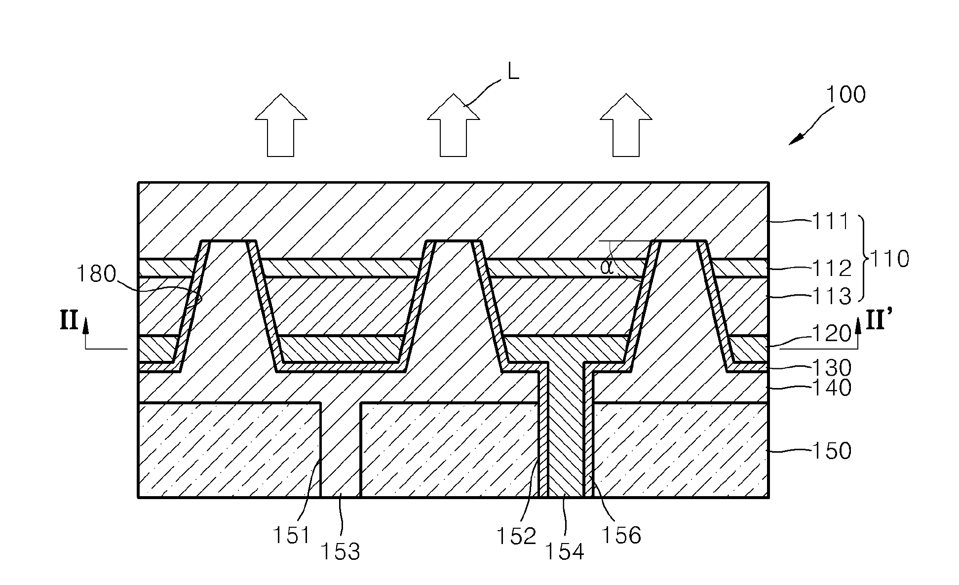
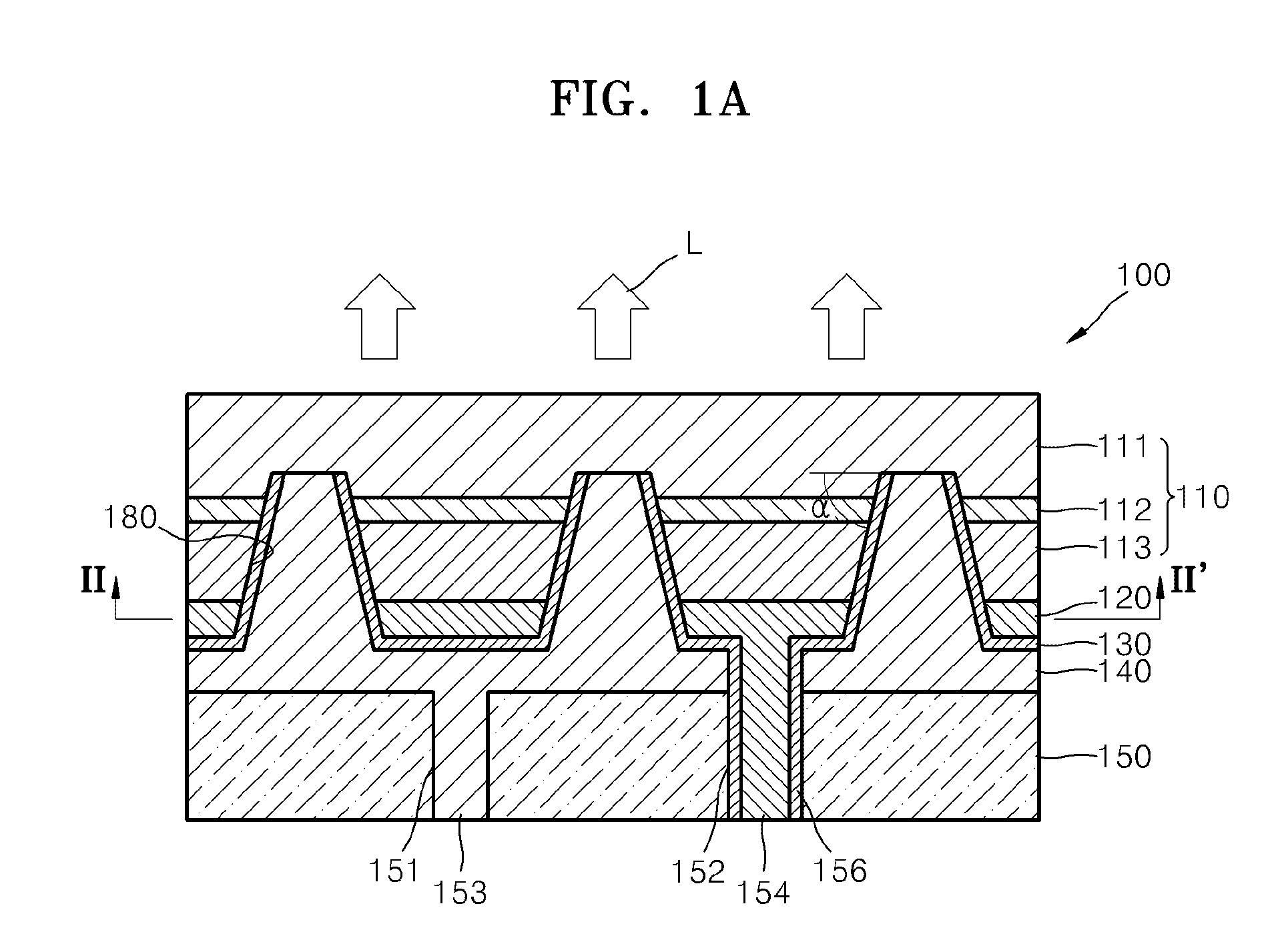
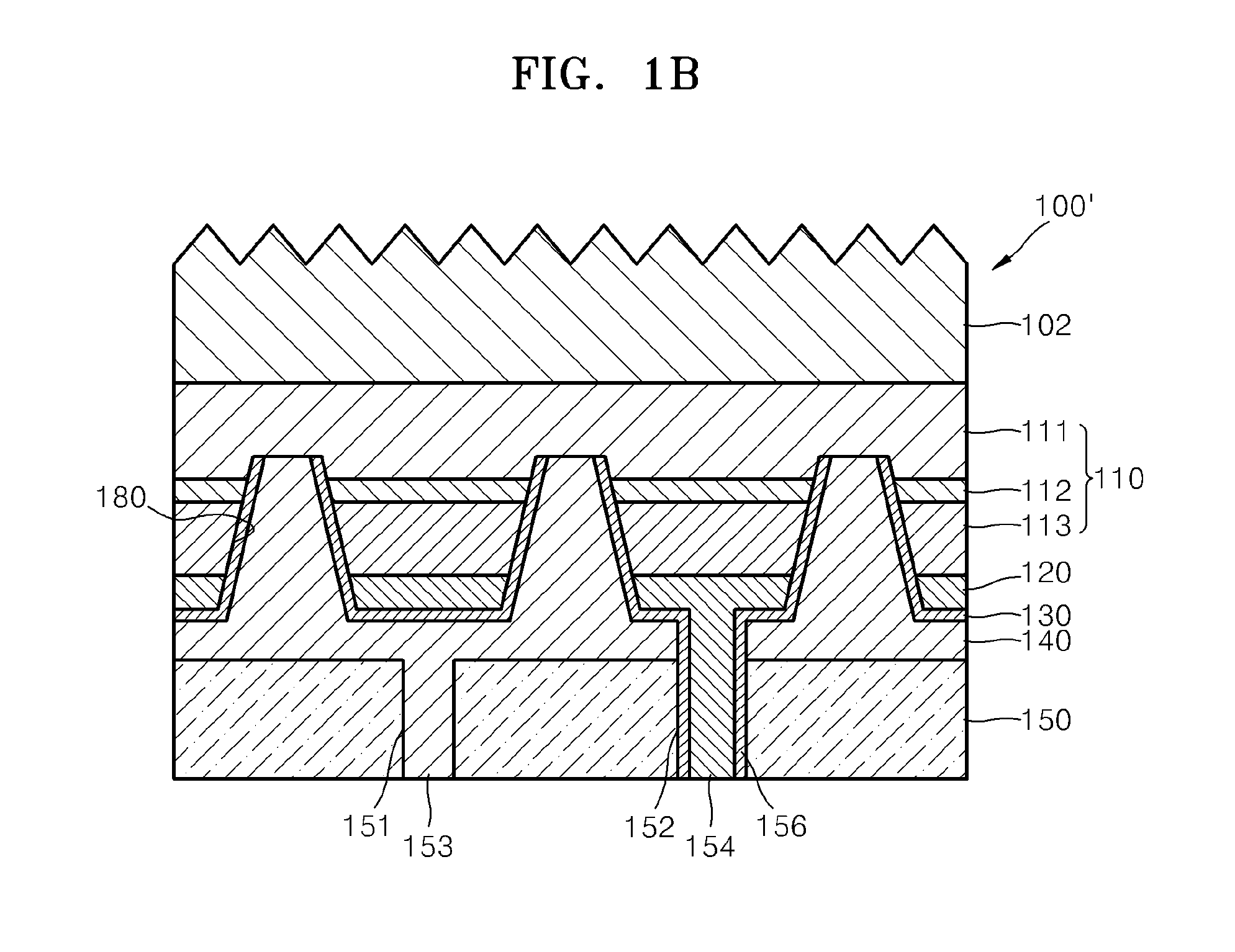
[0057]FIG. 1A is a cross-sectional view illustrating a semiconductor light-emitting device 100 according to an embodiment of the present invention. FIG. 1B is a modified example of the semiconductor light-emitting device 100 of FIG. 1A. FIG. 2 is a cross-sectional view taken along line II-II′ of FIG. 1A.

[0058]Referring to FIGS. 1A and 2, the semiconductor light-emitting device 100 includes a semiconductor structure 110, an electrode structure disposed on one surface of the semiconductor structure 110, and a substrate supporting the electrode structure.

[0059]The semiconductor structure 110 includes a subs...


PUM


Abstract

A semiconductor light-emitting device, and a method of manufacturing the same. The semiconductor light-emitting device includes a first electrode layer, an insulating layer, a second electrode layer, a second semiconductor layer, an active layer, and a first semiconductor layer that are sequentially stacked on a substrate, a first contact that passes through the substrate to be electrically connected to the first electrode layer, and a second contact that passes through the substrate, the first electrode layer, and the insulating layer to communicate with the second electrode layer. The first electrode layer is electrically connected to the first semiconductor layer by filling a contact hole that passes through the second electrode layer, the second semiconductor layer, and the active layer, and the insulating layer surrounds an inner circumferential surface of the contact hole to insulate the first electrode layer from the second electrode layer.

Description

CROSS-REFERENCE TO RELATED APPLICATIONS[0001]This application claims the benefit of Korean Patent Application Nos. 10-2010-0065967 filed on Jul. 8, 2010, 10-2010-0075670 filed on Aug. 5, 2010, and 10-2010-0079225 filed on Aug. 17, 2010 in the Korean Intellectual Property Office, the disclosure of which is incorporated herein in its entirety by reference.BACKGROUND[0002]1. Field[0003]The present disclosure relates to light-emitting devices in which an electrode for supplying current to a semiconductor layer light-emitting device is formed on lower surface of a substrate, and methods of manufacturing the light-emitting devices.[0004]2. Description of the Related Art[0005]In general, a light-emitting device such as a light-emitting diode (LED) has a junction structure between a p-type semiconductor and an n-type semiconductor. Such a light-emitting device may be classified into a horizontal light-emitting device and a vertical light-emitting device according to a position of an electro...

Claims


Application Information

Patent Timeline
Patent Type & Authority Applications(United States)
IPC IPC(8): H01L33/36H01L33/30H01L33/00H01L33/60
CPCH01L33/0079H01L33/20H01L33/382H01L33/405H01L33/44H01L33/32H01L2933/0016H01L2933/0066H01L2924/0002H01L33/62H01L2924/00H01L33/0093H01L33/0025H01L33/005H01L33/387H01L33/007
Inventor YANG, JONG-INKIM, TAE-HYUNGLEE, SI-HYUKSONG, SANG-YEOBSONE, CHEOL-SOOKIM, HAK-HWANLEE, JIN-HYUN
Owner SAMSUNG ELECTRONICS CO LTD
Learn More