3D Memory Array With Improved SSL and BL Contact Layout

a memory array and contact layout technology, applied in the field of 3d memory arrays, can solve the problems of limiting the use of technology, limiting the number of control gates that can be layered in this way, and high manufacturing cos

Active Publication Date: 2012-01-12
MACRONIX INT CO LTD
View PDF3 Cites 130 Cited by
  • Summary
  • Abstract
  • Description
  • Claims
  • Application Information

AI Technical Summary

Problems solved by technology

So, although the benefits of higher density are achieved using 3D arrays, the higher manufacturing costs limit the use of the technology.
Also, there is a limit in the number

Method used


Image

  • 3D Memory Array With Improved SSL and BL Contact Layout
  • 3D Memory Array With Improved SSL and BL Contact Layout
  • 3D Memory Array With Improved SSL and BL Contact Layout

Examples


Embodiment Construction

[0064]A detailed description of embodiments of the present technology is provided with reference to the Figures.

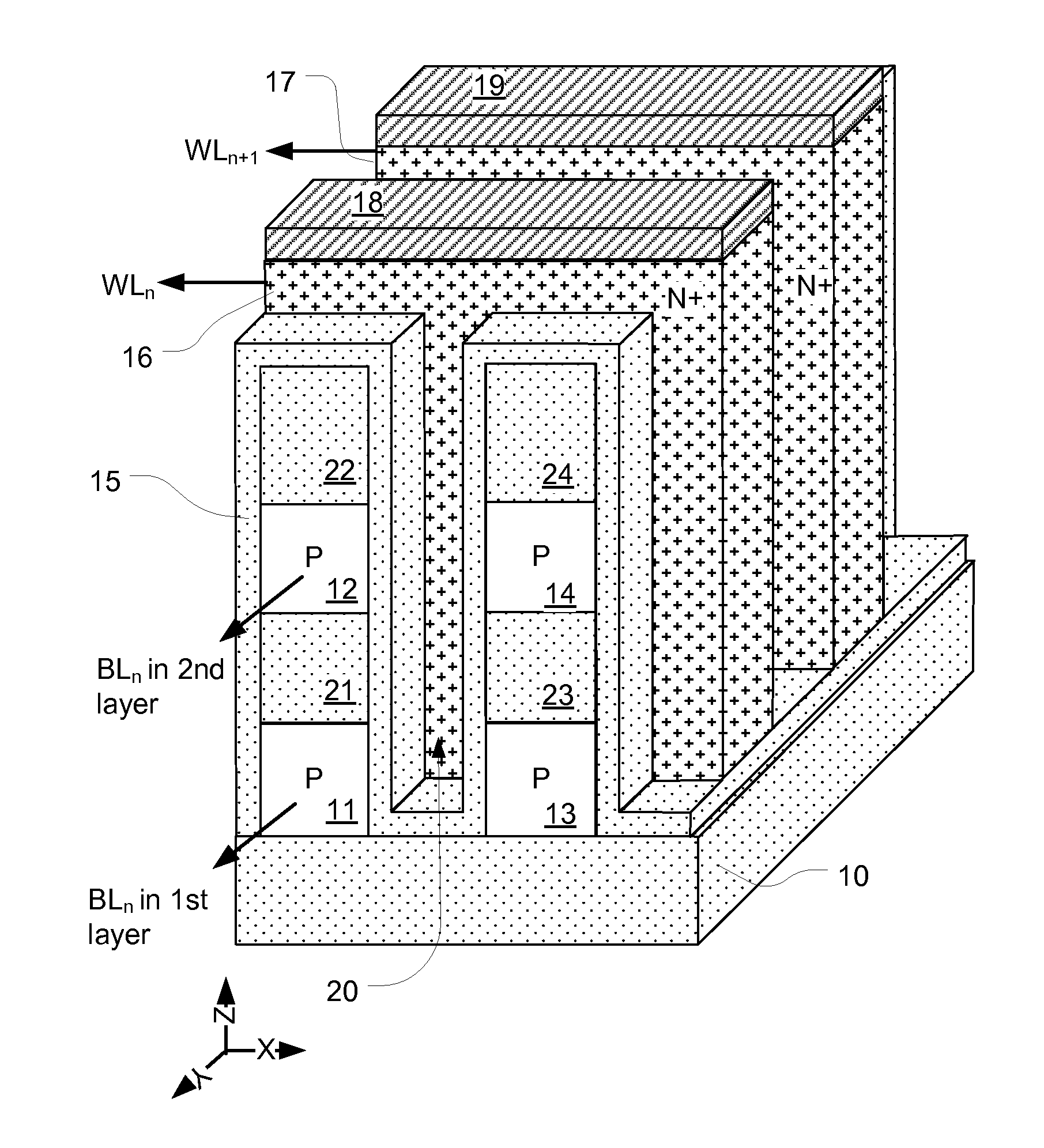
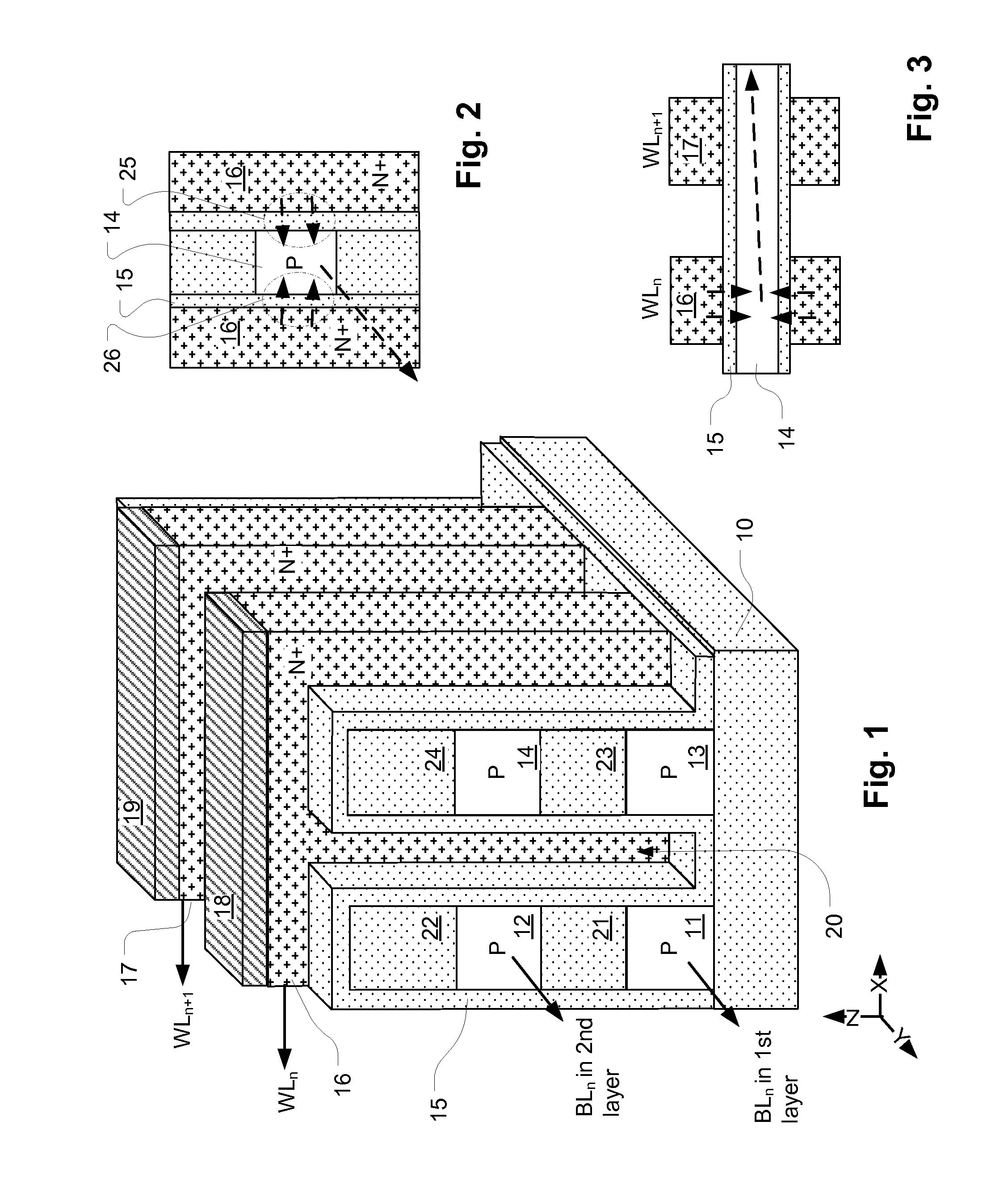
[0065]FIG. 1 is a perspective drawing of a 2×2 portion of a three-dimensional programmable resistance memory array with fill material removed from the drawing to give a view of the stacks of semiconductor material strips and orthogonal conductive lines that make up the 3D array. In this illustration, only 2 planes are shown. However, the number of planes can be extended to very large numbers. As shown in FIG. 1, the memory array is formed on an integrated circuit substrate having an insulating layer 10 over underlying semiconductor or other structures (not shown). The memory array includes a plurality of stacks of semiconductor material strips 11, 12, 13, 14 separated by insulating material 21, 22, 23, 24. The stacks are ridge-shaped oriented along the Y-axis as illustrated in the figure, so that the semiconductor material strips 11-14 can be configured as bit lines, and e...


PUM


Abstract

A 3D memory device includes a plurality of ridges, in some embodiments ridge-shaped, in the form of multiple strips of conductive material separated by insulating material, arranged as bit lines which can be coupled through decoding circuits to sense amplifiers. The strips of conductive material have side surfaces on the sides of the stacks. A plurality of conductive lines arranged as word lines which can be coupled to row decoders, extends orthogonally over the plurality of stacks. The conductive lines conform to the surface of the stacks. Memory elements lie in a multi-layer array of interface regions at cross-points between side surfaces of the semiconductor material strips on the stacks and the conductive lines. The memory elements are programmable, like the anti-fuses or charge trapping structures. In some embodiments, the 3D memory is made using only two critical masks for multiple layers. Some embodiments include a staircase-shaped structure positioned at ends of the semiconductor material strips. Some embodiments include SSL interconnects on a metal layer parallel to the semiconductor material strips, and further SSL interconnects on a higher metal layer, parallel to the word lines.

Description

REFERENCE TO RELATED APPLICATION[0001]This application claims the benefit of U.S. Provisional Application No. 61 / 361,623, filed on 6 Jul. 2010 and is incorporated herein by reference.RELATED APPLICATION[0002]This application is related to U.S. application Ser. No. 12 / 692,798, filed on 25 Jan. 2010 incorporated herein by reference.BACKGROUND[0003]1. Field[0004]The present technology relates to high density memory devices, and particularly to memory devices in which multiple planes of memory cells are arranged to provide a three-dimensional 3D array.[0005]2. Description of Related Art[0006]As critical dimensions of devices in integrated circuits shrink to the limits of common memory cell technologies, designers have been looking to techniques for stacking multiple planes of memory cells to achieve greater storage capacity, and to achieve lower costs per bit. For example, thin film transistor techniques are applied to charge trapping memory technologies in Lai, et al., “A Multi-Layer S...

Claims


Application Information

Patent Timeline
IPC IPC(8): H01L29/792H01L21/8239
CPCG11C13/0002H01L29/4234G11C17/16G11C2213/71H01L27/0207H01L27/0688H01L27/101H01L27/1021H01L27/11578H01L29/66833H01L29/792H01L21/768H01L23/5252H01L27/2481G11C16/0483H01L2924/0002H10B43/20H01L2924/00H01L29/513H10B63/84
Inventor HUNG, CHUN-HSIUNGLUE, HANG-TINGSHEN, SHIN-JANG
Owner MACRONIX INT CO LTD
Why Eureka
Try Eureka