
Resonator filter

a filter and resonator technology, applied in the field of filters, can solve the problems of weak coupling strength of the resonator in question, narrowing the band, and insufficient precision of the manufacturing process, and achieve the effects of large adjusting range for strength, filter bandwidth, and automatic tuning

Inactive Publication Date: 2012-01-12
INTEL CORP
View PDF4 Cites 9 Cited by
  • Summary
  • Abstract
  • Description
  • Claims
  • Application Information

AI Technical Summary

Benefits of technology

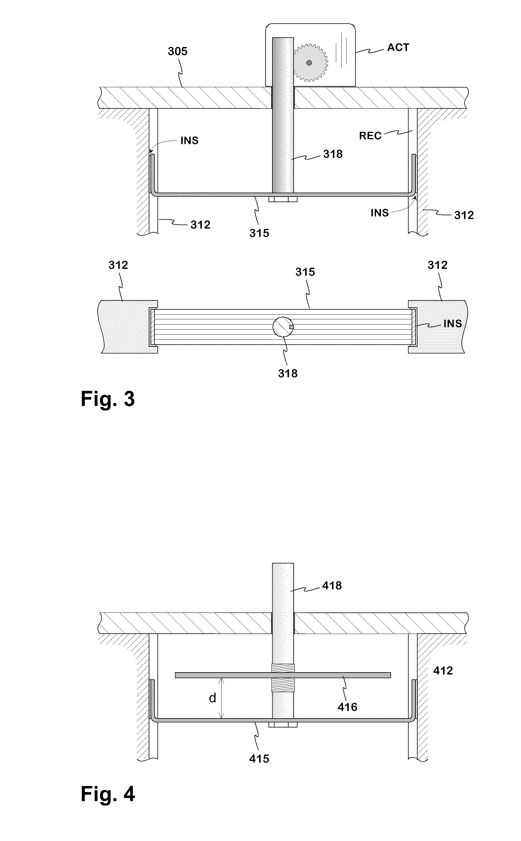
[0011]An advantage of the invention is that the tuning of a filter can be automated, in other words the tuning can be done without laborious manual work. In this case the measurement device of the response is programmed so that it steers the actuators of the filter to move the tuning elements until the optimal response has been achieved. In addition, the invention has the advantage that in a filter according to it the grounding coupling of the tuning element can be implemented as capacitive, in which case the rise of the passive intermodulation is avoided in the adjusting mechanism because of the lack of metallic junctions. A further advantage of the invention is that a structure according to it enables a relatively large adjusting range for the strength of the coupling between the resonators and thus for the bandwidth of the filter.
is that the tuning of a filter can be automated, in other words the tuning can be done without laborious manual work. In this case the measurement device of the response is programmed so that it steers the actuators of the filter to move the tuning elements until the optimal response has been achieved. In addition, the invention has the advantage that in a filter according to it the grounding coupling of the tuning element can be implemented as capacitive, in which case the rise of the passive intermodulation is avoided in the adjusting mechanism because of the lack of metallic junctions. A further advantage of the invention is that a structure according to it enables a relatively large adjusting range for the strength of the coupling between the resonators and thus for the bandwidth of the filter.

Problems solved by technology

In practice, the manufacturing process is not precise enough, for which reason the filter must be tuned before adoption.
When turning e.g. a tuning screw for coupling adjustment deeper to a coupling opening, which is located in the upper part of the filter, the strength of the coupling between the resonators in question weakens, which has the effect of narrowing the band.
A flaw of the use of the tuning screws is that the junction between them and the surrounding metal can cause harmful passive intermodulation when the filter is in use.
In addition, the electric contact in the threads can degrade in the course of time, which results in change in the tuning and increase in the losses of the resonators.
The flaw of such a solution is that in a multiresonator filter the tuning elements may possibly have to be bent in several steps in order to achieve the desired frequency response.
The lid of the filter has to be opened and closed for each adjustment, for which reason the tuning is time-consuming and relatively expensive.
A drawback of the solution described before is that the tuning of the bandwidth has been designed to be manual.
The automatic tuning by using actuators is difficult to implement.

Method used


Image

  • Resonator filter
  • Resonator filter
  • Resonator filter

Examples


Embodiment Construction

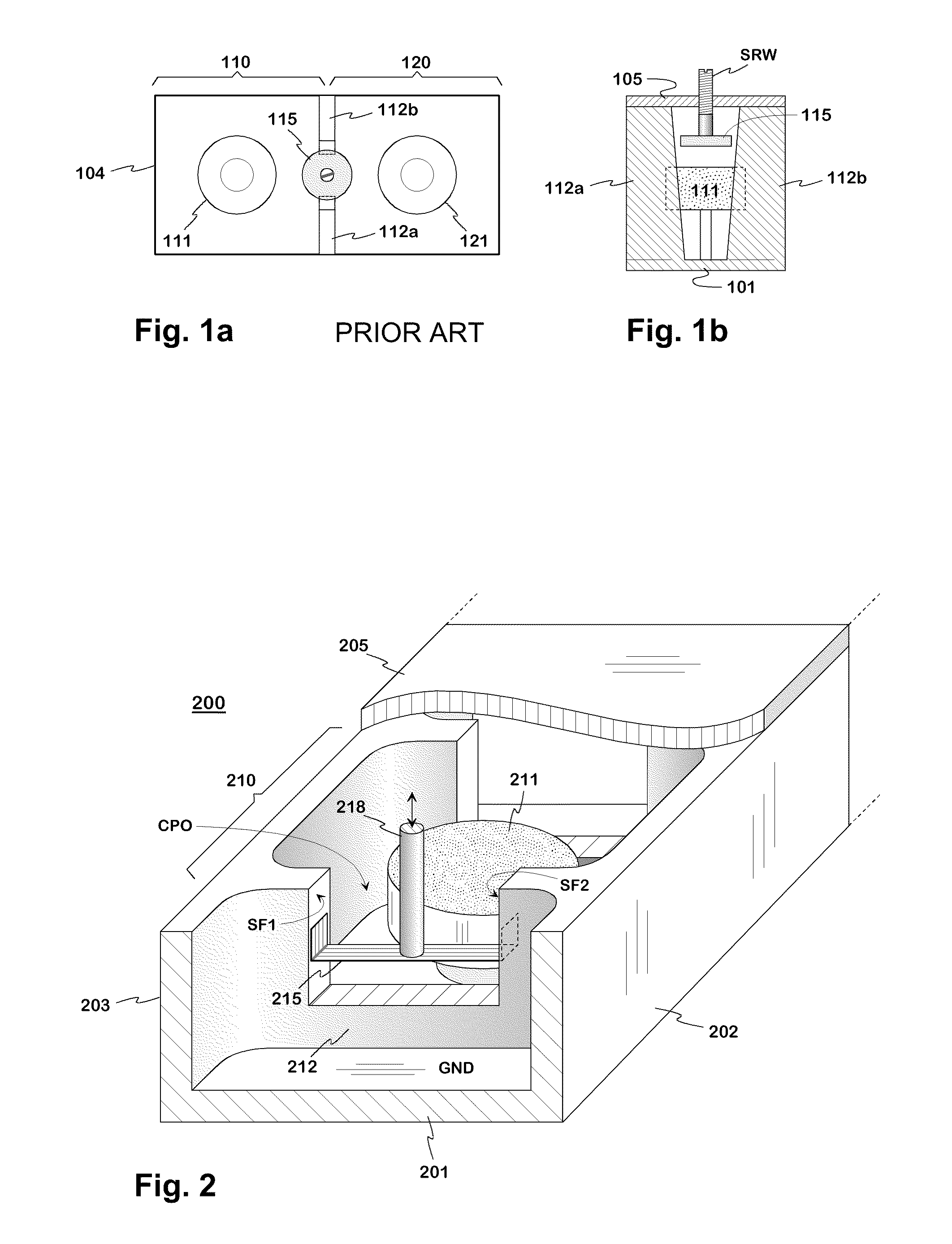
[0021]FIGS. 1a and 1b were already explained in connection with the description of the prior art.

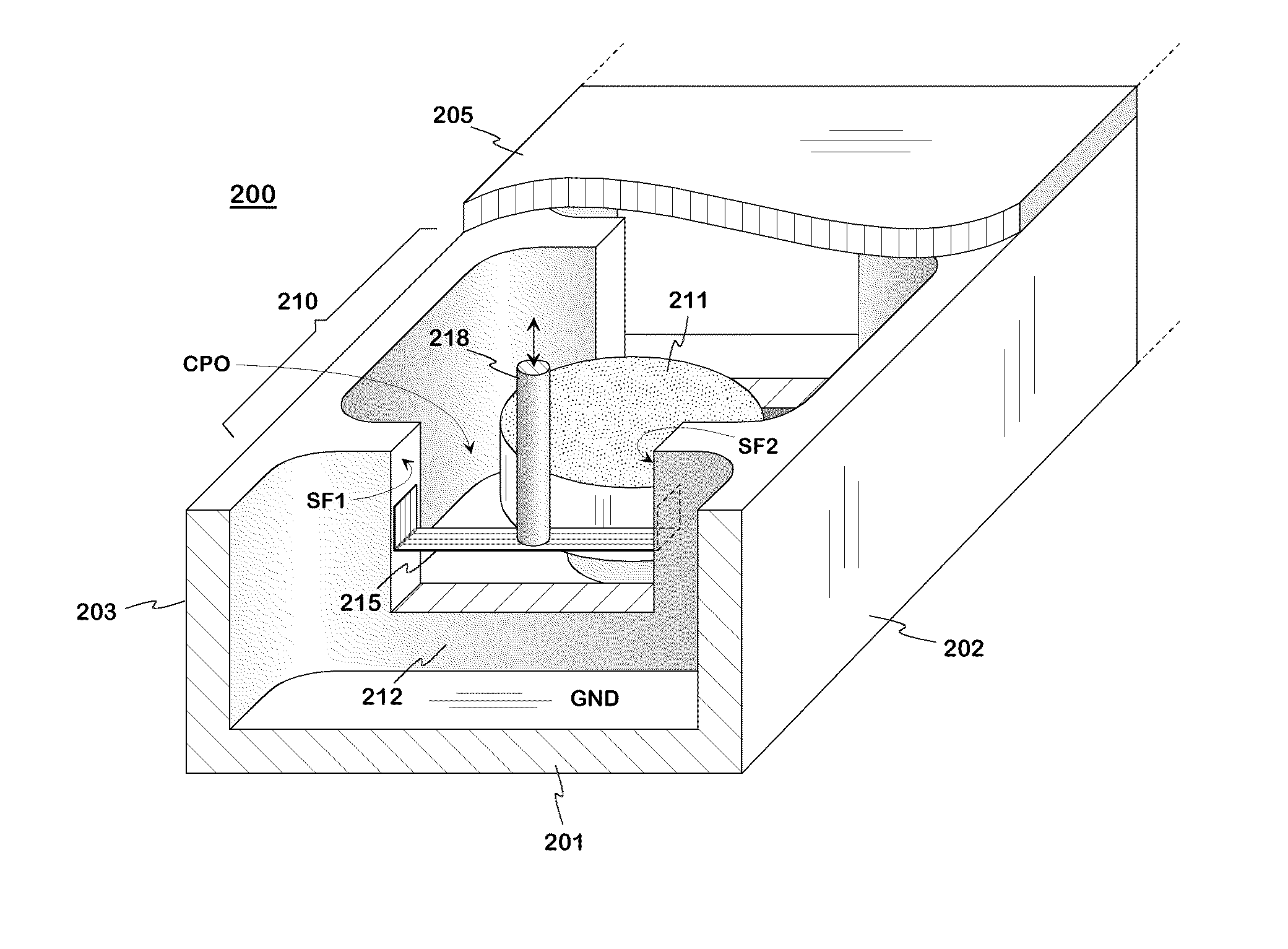
[0022]FIG. 2 shows an example of the tuneable filter according to the invention. The filter 200 comprises a conductive housing formed by a bottom 201, side walls 202, 203, head walls, and a lid 205. The space of the housing is divided into the resonator cavities by conductive partition walls 212 and in each partition wall separating two successive cavities there is a coupling opening CPO. In the drawing the filter has been truncated and the lid cut open so that only the cavity of a first resonator 210 is seen entirely, and the coupling opening between the first and second resonator is visible. When the filter is in use, its housing is a part of the signal ground GND of the transmission path.

[0023]In each resonator cavity there is a cylindrical dielectric resonator object for making the whole resonator smaller, such as the dielectric resonator object 211 of the first resonator 210. The ba...


PUM


Abstract

A tuneable resonator filter consisting of cavity resonators. In the partition wall separating the successive resonators on the transmission path of a resonator filter there is a coupling opening (CPO) with a typically constant width. The coupling strength between the resonators is adjusted by a tuning element which is supported to the partition wall on the opposite sides of the coupling opening so that it can be moved. The tuning element is conductive and grounded so that the impedance between its ends and the partition wall is low. For moving the tuning element, it is linked by a dielectric rod to an electrically controllable actuator being located on the filter lid. By means of the tuning mechanism the bandwidth of a filter can be set automatically.

Description

BACKGROUND OF THE INVENTION[0001]The invention relates to a filter consisting of cavity resonators, in which filter the couplings between the resonators can be adjusted. A typical application of the invention is an antenna filter in a base station of a cellular network.[0002]In order that the frequency response of a bandpass filter complies with the requirements, its passband must on the one hand be located at the right place on the frequency axis and on the other hand be of the right width. In a resonator filter this requires that the resonance frequency, or natural frequency, of each resonator is right and in addition the strength of the couplings between the resonators is right. In serial production, a filter consisting of cavity resonators is naturally formed by mechanical dimensions so that these requirements are realized as fully as possible. In practice, the manufacturing process is not precise enough, for which reason the filter must be tuned before adoption.[0003]In tuning,...

Claims


Application Information

Patent Timeline
IPC IPC(8): H01P1/20
CPCH01P1/2084H01P1/2053H01P7/10H01P1/205
Inventor TIIHONEN, MARKKU
Owner INTEL CORP
Learn More